Hmm... I would not use a socket but simply solder and then stand the IC up, in other words carefully bend the legs 90 degrees. Now you only need a single wire to pin 8. pins 5, 6 and 7 can be linked super neatly on the chip itself.
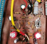
so first one done and it works a treat
might just tidy the underneath up a bit, but it isnt too bad
rails were still too high with 220k so i played around a bit and settled on 100k
so rails are +/-18.7v
might just tidy the underneath up a bit, but it isnt too bad
rails were still too high with 220k so i played around a bit and settled on 100k
so rails are +/-18.7v
Attachments
so thanks again @Mooly
Ive realy learned alot with this one, proberbly more than anything so far.
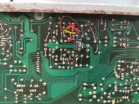
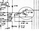
I had an issue with the second one, and although it was working , i only had 6v on pin 8, so i had lost one of the rails
so i assumed, as it was working but distorted, it was working as a half rail, and this was causing crossover distortion?
i found the issue anyway it was broken print
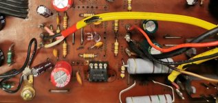
I think it looks quite neat
so all done 🙂
now to try it out on my speakers in the lounge👍
Ive realy learned alot with this one, proberbly more than anything so far.
I had an issue with the second one, and although it was working , i only had 6v on pin 8, so i had lost one of the rails
so i assumed, as it was working but distorted, it was working as a half rail, and this was causing crossover distortion?
i found the issue anyway it was broken print
I think it looks quite neat
so all done 🙂
now to try it out on my speakers in the lounge👍
Attachments
You're welcome 🙂
That looks really good 👍 but is the lower opamp correct? Top one has pin 1 to pad 1 but the other looks to be pin 8 to pad 1.
Broken print causes all kinds of weird faults.
That looks really good 👍 but is the lower opamp correct? Top one has pin 1 to pad 1 but the other looks to be pin 8 to pad 1.
Broken print causes all kinds of weird faults.
Your right it would have been. But if you notice the first one I moved up into space where some of the components that were not required left space, and I was able to use the original pin positions 1 to 4,but to enable me to do that on the 2nd would have meant moving resistors and caps, so the second one is 100% wired underneath
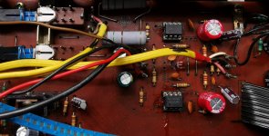
That side of things should all work just the same if you were to leave the resistors in place, however the Laterals do not need those 0.33 ohms as you know with the NAD's. I would just leave the transistor, if you link the 0.33 ohm out then the transistor is permanently off.
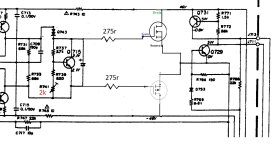
That looks OK. Remember the bias generator might need tweaking to get the bias voltage low enough for the FET's.
I might try it with the drivers in first. Also this amp is alot more powerful than the Nads I did, so will I need the 20n/p20,rather than the 10's?
I think the 10's will be just fine. A single pair is good for 100wrms at rails higher than the Marantz uses. Heat is the big problem with any amp and that is actually higher with the double die parts because you should bias them to twice the value of the singles.
- Home
- Amplifiers
- Solid State
- Odd things going on with a Marantz PM500