ok so there you go, it works with that opamp, so the ones i brought were,well 'no good' to be polite
rail was just a broken connection on RE19
This has been a realy worthwhile excercise for me this as it realy has got me learning and understanding better op amp operations, realy appreaciate it, thanks 👍
rail was just a broken connection on RE19
This has been a realy worthwhile excercise for me this as it realy has got me learning and understanding better op amp operations, realy appreaciate it, thanks 👍
Last edited:
Well that's something 🙂 All these old parts are long obsolete and fakes are rife. The theory didn't fail... everything pointed to a problem with the chip.
If you are happy with the result then just keep the 5532's although I would look at reducing the rails a little so the total across pin 8 and 4 is no more than around -/+20 volts. It doesn't matter if one rail is higher than the other, its the total that matters. -/+22 is the absolute limit but it might be wise to come down a fraction on that.
If you are happy with the result then just keep the 5532's although I would look at reducing the rails a little so the total across pin 8 and 4 is no more than around -/+20 volts. It doesn't matter if one rail is higher than the other, its the total that matters. -/+22 is the absolute limit but it might be wise to come down a fraction on that.
the chip has a +/- 3v tolerance on it so it may be ok.
Im running that channel at the moment without the rail reduced
Im running that channel at the moment without the rail reduced
just so i know why for the future
why did you connect pins 6 and 7 together
what was the purpose of disconnecting CE07 and CE13 and RE07
why did you connect pins 6 and 7 together
what was the purpose of disconnecting CE07 and CE13 and RE07
Its up to you, -/+22v is shown as an absolute max. Given that is so easy to drop the rails a bit it would be worth doing imo.
Pin 7 to pin 6 connects the other opamp in the package as a buffer (100% feedback) and tying pin 5 to pin 1 (look at the image I drew earlier) means the second opamp simply buffers the output of the first.
It is not good to leave the unused opamp not connected as it might do weird things such as draw to much current, get hot, generate noise and so on. So we tie it harmlessly out of the way. You could connect pin 5 to ground if it is nearer of more convenient.
There are so many opamps available today that its easy to get carried away. Its a very high performance opamp but that comes with penalties such as needing care in layout and decoupling, in other words it is more difficult to ensure stability. It might only be available in SMD outline and it uses a lower supply voltage.
The 5532 is old but extremely good for simple gain blocks like we use in audio.
If you keep the 5532 then just do a quick check that the voltage across the input coupling cap CE01, the output cap CE15 and the feedback return cap (which doesn't seem to have a number) all agree with the cap polarity markings. These are just small offset voltages but a different chip may give different offset polarities. The output offset on pin 1 might be a bit higher than you imagine with a 5532 but its normal when the input resistances are very unequal.
LM4562, the 5532 successor and much lower offset.
That's it for now 🙂
why did you connect pins 6 and 7 together
what was the purpose of disconnecting CE07 and CE13 and RE07
Pin 7 to pin 6 connects the other opamp in the package as a buffer (100% feedback) and tying pin 5 to pin 1 (look at the image I drew earlier) means the second opamp simply buffers the output of the first.
It is not good to leave the unused opamp not connected as it might do weird things such as draw to much current, get hot, generate noise and so on. So we tie it harmlessly out of the way. You could connect pin 5 to ground if it is nearer of more convenient.
what do you think of this as an alternative?
There are so many opamps available today that its easy to get carried away. Its a very high performance opamp but that comes with penalties such as needing care in layout and decoupling, in other words it is more difficult to ensure stability. It might only be available in SMD outline and it uses a lower supply voltage.
The 5532 is old but extremely good for simple gain blocks like we use in audio.
If you keep the 5532 then just do a quick check that the voltage across the input coupling cap CE01, the output cap CE15 and the feedback return cap (which doesn't seem to have a number) all agree with the cap polarity markings. These are just small offset voltages but a different chip may give different offset polarities. The output offset on pin 1 might be a bit higher than you imagine with a 5532 but its normal when the input resistances are very unequal.
LM4562, the 5532 successor and much lower offset.
That's it for now 🙂
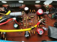
so ive decided to modify using 2 no 5532, and ill post the progress on here as I go as there isn't a lot of room to locate the bases , so it may be with or without, but it will be an interesting one
I'm sure the 5532 will perform every bit as well as the original, so yes, sounds like a plan. One thing to bear in mind if you replace several IC's is to be aware of total power consumption. The 5532 draws around 15ma from memory which should be OK for a couple of them. It may not sound much but it adds up if you replace a few. Check the regulators have enough headroom and still run cool enough.
so this is what i have to work with
I could find another new position, but i would prefer, at least to start with explore utilising the existing area if i can
I think it is possible, i just need to ensure it doesn't look a real mess by doing it.
These boards just do not exist anymore, even as old spares from wrecked amps, and those wrecks are still £200+ (and they are in America) https://www.ebay.co.uk/itm/255806091198?hash=item3b8f3b2fbe:g:2MUAAOSw-~9ge661
Attachments
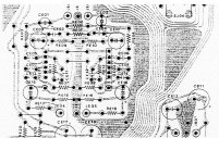
It is really important to keep the inputs as close as possible to the original positions to prevent stray noise pickup. The 5532 should look neat enough.
Donberg have the originals but to expensive imo:
https://www.donberg.co.uk/descript/h/ha_1457.htm
Donberg have the originals but to expensive imo:
https://www.donberg.co.uk/descript/h/ha_1457.htm
Gain is totally independent of supply voltage. Also it doesn't matter if the rails are unbalanced such as (extreme example) +6v and -30 volts. The rails define the maximum output voltage and so the voltage it will clip at.
Well it will reduce the maximum output voltage swing to a little below -/+20 volts but when you consider the opamp will be outputting signal voltages more in the low single volt range it is not going to make any difference at all. Measure it with your scope when its working and you will see the actual signal swing is pretty low.

- Home
- Amplifiers
- Solid State
- Odd things going on with a Marantz PM500