raikkonen,
I just go there:
http://app1.hongkongpost.com/CGI/mt/enquiry.jsp
It should work for you to.
Jean-Charles
I just go there:
http://app1.hongkongpost.com/CGI/mt/enquiry.jsp
It should work for you to.
Jean-Charles
Hi,
I made a tube output stage for this DAC.
It works very well. No need to envy the Nelson Pass i/v any more.
This amplifier delivers very good sound with solid bass and a lot of sound stage.
As with the Pass i/v, I got rid of almost all the anoying noise I was complaining about.
This is probably due to the fact that both, Pass and mine, have their own power supply and do not share a common supply as the NE5534 op amps on the DAC.
There is a small residual noise left however, but at maximum level only and I have to put my ears on the speakers to hear it.
As a perfectionnist, sure I would like to see it gone, but it would not change anything at listening level. I suppose that the filtering proposed by stefanobelianni would clean it completely.
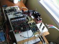
I wanted to post a photo of my set up, but it is too large and I could not join it here. I have to learn a way to reduce it a little to fit the standards of this forum.
If you have any suggestions, please explain me how to do this.
The Pass i/v and the tube amplifier are instaled side by side, with the DAC on a piece of plywood. I have two different sets of rca jacks with two pairs of cables that are connected to individual inputs on the preamplifier.
This makes easy to compare the two equipments. I just need to switch the input on the preamp and change the small input cable to JP6 on the DAC.
Jean-Charles
I made a tube output stage for this DAC.
It works very well. No need to envy the Nelson Pass i/v any more.
This amplifier delivers very good sound with solid bass and a lot of sound stage.
As with the Pass i/v, I got rid of almost all the anoying noise I was complaining about.
This is probably due to the fact that both, Pass and mine, have their own power supply and do not share a common supply as the NE5534 op amps on the DAC.
There is a small residual noise left however, but at maximum level only and I have to put my ears on the speakers to hear it.
As a perfectionnist, sure I would like to see it gone, but it would not change anything at listening level. I suppose that the filtering proposed by stefanobelianni would clean it completely.
I wanted to post a photo of my set up, but it is too large and I could not join it here. I have to learn a way to reduce it a little to fit the standards of this forum.
If you have any suggestions, please explain me how to do this.
The Pass i/v and the tube amplifier are instaled side by side, with the DAC on a piece of plywood. I have two different sets of rca jacks with two pairs of cables that are connected to individual inputs on the preamplifier.
This makes easy to compare the two equipments. I just need to switch the input on the preamp and change the small input cable to JP6 on the DAC.
Jean-Charles
Hi Jean-Charles,
I would like to try the tube output stage. Can you supply me with parts list and schematics?
I would like to try the tube output stage. Can you supply me with parts list and schematics?
...............I made a tube output stage for this DAC.......................
What tube and what supply V and Ip ?
Cheers.
Hi everybody,
Thank you fedde, I have downloaded irfan and I will learn how to use it.
I am new at posting on this forum and there are many things I do not know yet. I want to post this photo for the information of course, but there is also a learning process, to be able to post other informations, like schematics for instance.
kip, you got your answer above. I must learn how to do it.
ashok, I started the design with the 12AU7 in mind, but I switched to the 6DJ8. All explanations will come when I will post the shematics.
Jean-Charles
hi J charles,
very thanks for your helpful.
I gone to china for three days.
Do something about the dac,
first was testing the new program running for full balance dac.
sec was I funish the tube buffer already. I choose 5687 tube for the cathode followe of the dac, Standard parts of the dac.
I found out the HF noise was come from the XO of the re-clock, Can U try it. If U had one better Xo on hand, pls directly solder into the PCB. plug into socket & cause oscillation in my test. Added one filer of the ac input also canb improve too.
My 5687 cathode follower will running in 250V 10ma. Output caps use 0.33~0.47uf. I test one NOS EORID caps was quite good. If U had this on hand, pls try I feel quite good.
what is your tube output stage
design??? My 5687 cathode follow was running in B+250v,10ma. I don't like 6DJ8 low volatge tube buffer. any comment for this??.
can we share experience. I still under correction of the dac. Hope to make it more profect because Full balance will be my last version of 1541a dac!!!!!
thx
thomas
Hi,
small update of the ultimate ver.3 DAC.
1. AC inlet added filter Tokin ac filter.
2. 5687 cathode follower tube buffer, every dac use one tube only. Tube follow to the dac will Date 1959 NOS CSF OEM to IBM 5687 tube. I test for many tubes, two triode was very close.
5687 was made in France.
3. Op-amp will choose op-627 & 5534 will follow to dac too. since I test it in at least 5 place for different set up for horn & voice coil speaker. In horn set up 5534 will better. If in volice coil set up such as Jmlab, Op-627 will better. so I follow all for them so diyers can flexible to changwe trhe sound stage.
4. relayout to lower the noise & test will headphone to pass the noise level.
5. Total will 6 pcs of the PCB??
1.1541a DAC with re-clock & IV ( OP).
2. Complex power supply for totally 9 section of power supply to dac. increase the current supply of the Power supply Board which will stable to use parallel two 1541a chips.
3. standard USB receiver was PCM2906.
4. Signal selection Board contain 3 pcs. 1. MCU control source input with relay control 2, MCU control with LED display. Sockets in the back panel.
5. Extra 1541a PCB with regular power supply & coupling caps.
6.All funish & test already.
7. use triode power transformers
thx
thomas
Hi,
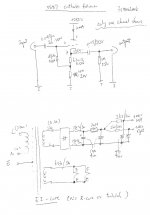
When I initiated this project, I had in mind to use the 12AU7 tube.
I like the sound of this tube and I have plenty here.
Among all the topologies available, this new one, proposed by M. Chi C. Wong, realy caught my attention.
Due to current source, both tube sections see a high impedance load establishing ideal conditions for the two of them. This lowers distortion and output impedance.
I selected an acceptable operation point at 4.7 m.a. to use a J511 current source diode. A string of diodes in the cathode of the first tube sets the bias voltage. They also extend the bandwith. It is recommended to use 1N4181. I did not have any, so I used 1N4148 instead.
In all the design is simplified, requiring less parts, without introducing a noise problem.
I built then a first prototype.
The results were good, but some adjusments were needed. I was not completely satisfied, so I looked for alternatives.
Other tubes needed to change the bias (diodes) and did not offer much more gain, because I found that it was a bit low with the 12AU7.
Since the gain of the stage is approximately equal to the amplificatin factor of the tube I brought the 6DJ8 to the rescue.
The 6DJ8 has almost the same biasing conditions as the 12AU7 but with an amplification factor of 33.
This is exactly what we need for the DAC.
The second prototype proved to be much better than the first.
A nice surprise was to discover that the 6DJ8 produced a much better sound than the 12AU7 in this application.
That was so promissing that I decided to upgrade immediately with better components.
In the present prototype, R1,R2 are 82 ohm (thats what I had). R4,R5 are not present, it is shorted. The voltage is stable enough and signal is so low that I do not fear that the grid goes positive at any time. However, it is a good technique to have a resistor there, but I will check first if it has any impact on the sound. If any one of you try it before me, kindly inform us of the results.
I also would use first class resistors, like Caddocks for instance.
I used Solen's Tin film capacitors for the output. Any good high end film capacitors could do the job, I suppose.
A word on the power supply. I used what I had on hand.
The raw supply comes from a DIYClub TIP-13 regulator from Hong-Kong.
This is a 6X4 tube rectifier, folowed by a series FET regulator that I ajusted to 230V output.
There is also a LM317 regulator to provide filament voltage ajusted to 6.3V.
At this time I used a second regulation stage as John did in his design.
This is important and was suggested by Walt Yung, in his researches on power supplies for audio.
I like the tube rectifier, it adds delay and turns on the voltage slowly to the amplifier, giving the 6DJ8 enough time to warm up.
The amplifier works very well now in its present form and matches the DAC perfectly, so enjoy it!
Jean-Charles
Attachments
Hi Thomas,
There are tubes that in certain applications work well while they will not perform in others.
In the tube amp that I posted just before, the 6DJ8 is a sure winner over the 12AU7. I can not explain why.
In my Curcio preamp, I find the 12AU7 a better choice.
I do not have any other XO at present. Would you suggest me to solder the one that I have?
I work from my basement now. I still have very good equipment, mainly Tektronix and HP, but, like the operator, it is getting older every year!
I have been retired for over 13 years now and I do not have all the facilities, or easy access to parts, or services that the youngers have.
I do not stock anymore. I find it totaly useless.
Jean-Charles
hi Jean-Charles,
very thanks U share your precious experiences to all diyers. me too!!!! But your design was not same as me. I agreed that use tube rectifier will slow warm up for both tubes. But I little worry for the noise. Sec was I still suggest use cathode follower in HV (B+250 10ma) in 5687 beause this tube was strong. In my small little test test this tubes was quite powerful. Although cathode follower magnification factor was <1~approx 0.9. But the dynamic power was quite good. Is your circuit directly connect from the IV resistors of the 1541a or from the Op-amp!
I was prepare the 5687 circuit, since the original one was I hand write only. over 300K file, I cannot post into the forum.
thx
thomas
Thomas,
Thank you Thomas for your constructive comments in post 1112.
I would like to clarify a few points here.
First, let me repeat what I previously said. I used what I had on hand and I do not want to redesign what has been done so many times before.
I do understand your concerns with noise in tube rectifiers. But after the two stages of regulation and filtering that folows, I am not too worried about it. It does not show in the prototype I have built anyway.
I beleive it is important to delay the application of the high voltage on tube until the filaments have reached a proper operating temperature.
It could be done in many ways however, to avoid tube rectification if you want.
I did not say it yet, but I also favor a slow start for the filaments.
It could be done in steps, as John did, or through a slow ramp using resistor and capacitor controling the LM317.
The application notes on the LM317, in the data book, shows such a circuit.
All these precautions are designed to protect, extend the life of our valuable and expensive tubes.
In my younger age, I could buy a receiving tube for $0.25. Forget about that today!
A word about the tube amplifier design.
I think we should look at it as an ideal SRPP stage.
The bottom triode looks up to the current diode as a very high impedance, reducing distortion to a minimum.
The upper triode looking down to the same diode, sees also a very high impedance, making it an ideal cathode folower.
Of course we can go back to the classical SRPP stage, simply by replacing the diodes with appropriate biasing resistors for each section, with the advantages and the disavantages of such a configuration.
I found Wong's idea very creative and decided to give it a try in your DAC to replace the solid state buffer.
So I selected an operation point and parts accordingly.
I must tell you, it is working beautifully.
It gives your DAC a life it did not have before.
Of course, you are welcome to design your own, using the tube and settings of your choice.
But do not overlook this design.
You can swing between 40-50 V P-P of signal with less than 1% distortion, no feedback. Quite impressive!
For larger voltage swings, we would have to look for an other tube and deeper bias.
I wish you could modify, test, redesign the stage if you want, because you surely have better facilities than I have.
At last, I could go back playing golf and leave the nice, young EE like you, earn my living! LOL!
For simplicity, not wanting to modify your board, I put an other i/v resistor with the amplifier, dirrectly at the grid.
I removed the jumpers on JP6, used a small shielded cable with a 3 pin, .100 connector and go pick the signal dirrectly on JP6, TDA1541A side.
This way, I can remove easily this connection, put the jumpers back in and use the solid state buffer as before.
Let me see.
Yes! We have a beautiful sun shine here today.
Thomas, I will leave you with "all" the engineering problems and guess what I gonna do? LOL!
Enjoy yourself!
Jean-Charles
hi J charles,
I was so happ tha U teach me so much that my teacher not teach me.
Very thanks again for the comment & I will try.
This several days I did another experience again & hope can try to all diyers who using my ver.3 dac.
1. beside the output stage of the op-amp U will see a ground sign, pls only use the point directly ground to the chassis.
Pls did not use ore than one point ground & will cause a ground loop of the dac.
2. added a AC filter.
3. I will free to post one small PCB with one single op-amp since this was a LPF add into the output stage of the op-amp. The noise gone.
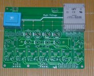
Hi, Charles, pls take a look of my 5687 tube buffer.
thx
thomas
I was so happ tha U teach me so much that my teacher not teach me.
Very thanks again for the comment & I will try.
This several days I did another experience again & hope can try to all diyers who using my ver.3 dac.
1. beside the output stage of the op-amp U will see a ground sign, pls only use the point directly ground to the chassis.
Pls did not use ore than one point ground & will cause a ground loop of the dac.
2. added a AC filter.
3. I will free to post one small PCB with one single op-amp since this was a LPF add into the output stage of the op-amp. The noise gone.
Hi, Charles, pls take a look of my 5687 tube buffer.
thx
thomas
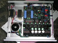
Attachments
Hi Jean-Charles,
Do you have a power supply schematic for the tube output? I am searching on EBay and don't know what transformer to purchase. I need more direction to built the tube I/V stage. I can read schematics, but not design. Where to a attach the input of the tube I/V stage to? Directly to the output of the dac?
Do you have a power supply schematic for the tube output? I am searching on EBay and don't know what transformer to purchase. I need more direction to built the tube I/V stage. I can read schematics, but not design. Where to a attach the input of the tube I/V stage to? Directly to the output of the dac?
Kip,
/
/
I removed the jumpers on JP6, used a small shielded cable with a 3 pin, .100 connector and go pick the signal dirrectly on JP6, TDA1541A side./
You will find part of your answer here in my previous post.
For the rest, it will be better to write you personnally.
Jean-Charles
- Status
- Not open for further replies.
- Home
- Group Buys
- non-profit ver.3 TDA1541a DAC for limited budget diyers