These are the settings I try, and wich are working.
Jumper: JP1 short, JP3 2-3 short, JP2 short
NOS mode
S2 - on off on on - JP4 close - JP5 close all - Clock out - SA7220 - out
NOS mode*
S2 - on off on on - JP4 open* - JP5 close all - Clock out - SA7220 out
NOS+SA7220
S2 - on off on on - JP4 close - JP5 open - Clock out - SA7220 in
NOS+Clock
S2 - off off on on - JP4 open - JP5 close all - Clock in - SA7220 out
NOS+Clock+SA7220
S2 - off off on on - JP4 open - JP5 1-close 2-3-4 open - Clock in - SA7220 in
NOS+Clock+SA7220*
S2 - off off on on - JP4 open - JP5 All open * - Clock in - SA7220 in
As you can see there are 2 mode for NOS and NOS+Clock+SA7220, but what are real ones...
Peter.
Yes, that was my guess. The filter chip uses a lot of energy then... 🙂
My experiences with the clock PCB are better now. Do you like to use the clock PCB?
Fedde
My experiences with the clock PCB are better now. Do you like to use the clock PCB?
Fedde
Hi Thomas,
As Idefixes pointed out, it is not the same cd rom contrller that you sent me. My buttons are on a separate pc board. I am having other problems with the cd rom controller besides the output to the dac question. It will play then that is all. No responce after that.
As Idefixes pointed out, it is not the same cd rom contrller that you sent me. My buttons are on a separate pc board. I am having other problems with the cd rom controller besides the output to the dac question. It will play then that is all. No responce after that.
Kip said:Hi Thomas,
As Idefixes pointed out, it is not the same cd rom contrller that you sent me. My buttons are on a separate pc board. I am having other problems with the cd rom controller besides the output to the dac question. It will play then that is all. No responce after that.
On my ASUS on CDROM drive I have an extra spdif output. I will use this to connect to the Dac.
Marc
Hi Thomas,
Thank you for the reply.
No, I am not absolutely sure the noise comes from the 5 Volt rail of the clock board. This is an assumption from my part. What I can tell is that if I put the clock board in operation we have noise generated.
I will hook an oscilloscope on it today and I will report to you.
I have tried a few things like changing the audio opamps, used good thin film caps at the output, the changes where not significant enough to report. It is already very good.
The sound is very similar to the equipment of reference, but it needs to be a little more transparent, not by much.
Do not worry about the sound, it is very good. I am impressed because I compared it with an YBA DAC and will do later against Sonic Frontier, Audio Research and Goldmund. All the above DACs cost many, many thousands of dollars and your DAC compares very well with them.
I know the differences between the YBA and other DACs, so I know in advance what to expect.
I suspected the noise to veil the sound a little, but that remains to be seen, no proof of that, yet.
With the 30db+ of gain in the op amps stage, any residual noise will be amplfied to audible levels easily.
I am happy to collaborate with you and report my observations to help in tweaking this DAC. It is real fun to see an equipment of this price almost equal the big expensive machines.
If it is easy to implement, I will try a 5V 5W zener ahead of U4 to reduce power dissipation and I will report to you if it does the job good enough.
Jean-Charles
Thank you Marc,
I may need another cd rom and I am up for suggestions. This may also be some of the issues I am having (older cd rom drive). I will try to lay low to see if anyone else has any of the same problems and what their solution and cd rom is.
I may need another cd rom and I am up for suggestions. This may also be some of the issues I am having (older cd rom drive). I will try to lay low to see if anyone else has any of the same problems and what their solution and cd rom is.
Work on DIY DAC chassis go foward
Black heathink will be scewed on the cahssis bottom to deal with U4 tempature. I will do the same chassis for the Drive base on CDROM+CDROM controler.
Marc
An externally hosted image should be here but it was not working when we last tested it.
An externally hosted image should be here but it was not working when we last tested it.
An externally hosted image should be here but it was not working when we last tested it.
Black heathink will be scewed on the cahssis bottom to deal with U4 tempature. I will do the same chassis for the Drive base on CDROM+CDROM controler.
Marc
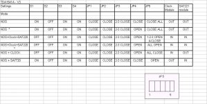
Here is the updated settings chart with Stevox's inputs.
The asterix is for settings which work but need some explanation ( does it ? ).
The diagram shows JP5 as seen on the board. Left of the JP5 print is pin 1 and right of JP5 print is pin 5.
That should clear up any doubts.
Cheers.
The asterix is for settings which work but need some explanation ( does it ? ).
The diagram shows JP5 as seen on the board. Left of the JP5 print is pin 1 and right of JP5 print is pin 5.
That should clear up any doubts.
Cheers.
Attachments
tube-lover said:hi RTD,
no no..... I send to france already in reg.mail RA18485047hk.
sorry I made a mistake that U also in USA.
thx
thomas
Hi Thomas,
Is this reg.mail reference Ok ? I cannot see it on mail tracking on Hong Kong Post website ?
Thx,
RTD
Hi Thomas,
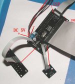
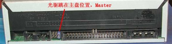
In the photo it shows a cable ISP with pin 1 at the top. I don't have that cable, nor a discription of where it connects to the dac ver.3. My cd rom is set to master and it does not have a spdif digital out. I am also having a communication issue with the rom. The cd controller can see the rom drive, shows when it is open and a cd is inserted, and I can then press play on the button or remote and the rom will play, but then that is all. Stop, pause, etc. will not respond and when I press eject the counter stops on the display, but it still says play. I then need to turn power off for it to work again, then the same happens.
In the photo it shows a cable ISP with pin 1 at the top. I don't have that cable, nor a discription of where it connects to the dac ver.3. My cd rom is set to master and it does not have a spdif digital out. I am also having a communication issue with the rom. The cd controller can see the rom drive, shows when it is open and a cd is inserted, and I can then press play on the button or remote and the rom will play, but then that is all. Stop, pause, etc. will not respond and when I press eject the counter stops on the display, but it still says play. I then need to turn power off for it to work again, then the same happens.
Hi thomas,
will be an extra keybord for button in the CDROM kits you will ship me? Not only one PCB with all button on. The internal height of my chassis is 55mm so it's much comfotable to implement when it's with the extra key bord.
Marc
will be an extra keybord for button in the CDROM kits you will ship me? Not only one PCB with all button on. The internal height of my chassis is 55mm so it's much comfotable to implement when it's with the extra key bord.
Marc
I've spent quite some time yesterday listening to the DAC and I'm REALLY pleased. Who would've thought it could sound so good? I compared it to my Marantz CDP5001 analogue stage and there was just no comaprison!!! I have picked up the digital noise problem that Jean has referred to, but it is VERY soft (I have to put my ear next to the speaker). I must be honest, though, that I would like to get it fixed if possible. I have not had time to fiddle with all the different settings, I've been enjoying the DAC too much ;-)
Thanks Thomas for offering us such a nice piece of kit at such a low price!! I'm really tempted to get the S2 chip, but it will have to wait unitl I finish my new amp and preamp...
Gert
Thanks Thomas for offering us such a nice piece of kit at such a low price!! I'm really tempted to get the S2 chip, but it will have to wait unitl I finish my new amp and preamp...
Gert
Hi Thomas,
Thank you very much, the parcel is arrived today, everything is ok, except you've forgotten the CD controler kit...
I don't know if OAP62BP or AD797 was included in the kit, I should have asked you before.
I know you have a lot of work and you don't earn money on these sales, so I'm ok to share shipping fee for the cd controler.
Thank you very much !
Nico
hi kip,
I understand what is the happen of the control, I hadn't test all cd-rom is it compatible to all CD-rom. I only test with ASUS & Plextor only. The best was plextor, more stable & more silent.
if the CD-rom was not compatible to control kit. This will be some function will not work.
thx
thomas
I understand what is the happen of the control, I hadn't test all cd-rom is it compatible to all CD-rom. I only test with ASUS & Plextor only. The best was plextor, more stable & more silent.
if the CD-rom was not compatible to control kit. This will be some function will not work.
thx
thomas
Hi Thomas,
Do you have a plexor model number? Do I need a spdif out on the cd rom? I purchased a thin internal ide laptop cd rom drive with an adapter to use with the 40 pin ide cable. The controller doesn't see it at all. The other cd rom is a 10 year old creative labs 4x cd rom.
Do you have a plexor model number? Do I need a spdif out on the cd rom? I purchased a thin internal ide laptop cd rom drive with an adapter to use with the 40 pin ide cable. The controller doesn't see it at all. The other cd rom is a 10 year old creative labs 4x cd rom.
hi kip,
normally the plextor all models will suitable for this because some of my friend all were use plextor cd or dvd /dvd/rw rom, also quite good for this.
the best was plextor was soft start up, the disk will not easy to damage.
thx
thomas
normally the plextor all models will suitable for this because some of my friend all were use plextor cd or dvd /dvd/rw rom, also quite good for this.
the best was plextor was soft start up, the disk will not easy to damage.
thx
thomas
Hi Thomas,
I know you are busy. I was hoping you could reply to my Q in post #931 on this thread about v2 dac. There is a pdf showing my 3 transformers attached to that post. I know what to do with secondary leads.
Are the brown or red leads of the transformer primaries POSITIVE or NEUTRAL? I know Black goes to chassis ground.
For 120vac in USA, should I solder all 6 red leads to one lug on a terminal strip, and then from this lug run 1 wire to IEC Hot or Neutral? Then I could solder all 6 brown leads to another terminal lug, and run one wire to other pin on IEC? Please advise.
- Status
- Not open for further replies.
- Home
- Group Buys
- non-profit ver.3 TDA1541a DAC for limited budget diyers