I hope and trust you also read that the set of PCBs sold in the Store, includes front and rear panels for the Galaxy 1U chassis (any & every depth), including pre-drilled holes and pre-printed labels / silkscreen. These panels are made of thick black PCB material, they are PCBs in fact; and they allow builders to complete the Noir without owning or using a drill press. Image from the Store's sales page attached below.
_
If you get the kit, the chassis comes with the solid front panel that you can use the PCB as a drill guide if you so choose. I personally like the solid black/thicker front panel so I went that route but my initial build used the PCB front panel that came with the kit and it works fine (and looks good)
--Tom
Wires obtained from CAT5 or 6 cable is absolutely my favorite for general chassis wiring.
Thanks for the confirmation. Speaking of amps, here's what I just received via the mail today:

The PCB kit was shipped quicker than I expected. Still waiting for all of the other parts.
hello, I have just discovered the STP16NF06 with this headphone amplifier, do you know an equivalent which supports more than 60v?
thanks
thanks
Here's a broadly similar 600V part.
SIHP100N60E-GE3
Why do you need the extra voltage? The rest of this circuit will certainly not scale with it...
SIHP100N60E-GE3
Why do you need the extra voltage? The rest of this circuit will certainly not scale with it...
Last edited:
Their "product selector" / parametric data table , is pretty good:
ST Microelectronics Power MOSFETS < 350V
There's another table for 351V to 700V MOSFETs here
ST Microelectronics Power MOSFETS < 350V
There's another table for 351V to 700V MOSFETs here
Here's a broadly similar 600V part.
SIHP100N60E-GE3
Why do you need the extra voltage? The rest of this circuit will certainly not scale with it...
HI, thanks for the part but SIHP100N60E-GE3 has 1851pf CIS
STP16NF06 has 314pf and 3S @2A transconductance which is very good
In fact it is not for the NOIR, but for a Circlotron headphone amplifier
Their "product selector" / parametric data table , is pretty good:
ST Microelectronics Power MOSFETS < 350V
There's another table for 351V to 700V MOSFETs here
Hi
thanks i looked but i didn't find anything as good as STP16NF06 more than 60v, i need 70v
DIY Noir Modification for 9dB of gain
I finally got around to modifying my Noir (T2) HPA for an increase in gain from 6dB to 9dB. This was done by modelling the circuit in LTSpice and then adjusting the values of R25(75), R26(76), R27(77) and R28(78). Original design has all of those resistors as 68 ohms. The values that gave 9dB gain in the model were:
R25(75), R26(76) = 47 ohms
R27(77), R28(78) = 91 ohms
Resistor power ratings were kept at 3 watts each. Bias was set by measuring the voltage across R27(77) and setting it to 6.82 VDC, which kept the bias at approximately 150mA per Mark's original spec. This is different from the 5.10 VDC setting used with the stock 68 ohm resistors. Temperature readings were:
Output devices = 52 deg C
R25(75), R26(76) = 52 deg C
R27(77), R28(78) = 60 deg C
With those temps, I don't see any long term reliability issues. Maybe Mark can chime in if he sees something I missed.
I also modelled the HPA at 12dB of gain but the circuit collapsed at about 14dB of gain and I felt that building a 12dB version would not leave enough margin of reliability. The 9dB version plays significantly louder than the extra 3dB of voltage gain would suggest. It now compares favorably in apparent gain with my other headphone amps. I see no need to push it further.
I was surprised at how the sonic signature changed. The original design sounds very good but is a bit laid back for my taste. The sound of the new version is more dynamic, perhaps at the expense of a very, very slight loss of smoothness in the upper range. The ranking of my HPAs had been:
Best = Whammy w/ OPA1612
2nd = BA2018 w/ large outputs
3rd = 6dB Noir
The 9dB Noir has moved up to position #2, beating out the BA2018. Although this mod might not be for everyone, I won't be putting the stock 68 ohm resistors back in. For a few dollars worth of parts and some time, you might just want to give it a try.
Congratulations, avdesignguru, and Good On Ya! It's wonderful that you are enthusiastic and confident enough to modify the design. And of course it's spectacular that your modifications worked as planned. You should be proud of this accomplishment.
With 75mA flowing in (R25 = 47 ohms) and 75mA flowing in (R27 = 91 ohms), the 91 ohm resistor will heat up more, since dissipated power = I*I*R. Running the numbers, I get 0.51 watts in R27.
Checking the datasheet for the 3W resistors specified in the Noir BOM, we see that the copper lead 3W resistor has a thermal resistance of 60 degrees K per watt, in their specific test fixture with their specific lead lengths and their specific PCB copper radiation area. So they expect the resistor to be (0.51 * 60) = 31 degrees K above ambient. Your result was (60 - 27(?)) = 33 degrees K above ambient. Damn fine agreement! Well done.
I agree with you: running 3W-rated resistors at an actual power dissipation of 0.51W, such that the resistor body temperature is 33 degrees above ambient air temperature, seems perfectly reasonable. There is plenty of safety margin.
Maybe it's not completely astonishing that your listening impressions changed a bit after modifying the circuit. But it's delightful to learn that the changes perhaps did more good than harm.
Applause and best wishes,
Mark
What was the reasoning behind changing the gain from 6db to 9db in the first place?
Was it for a harder to drive heaphone load?
Just wondering!
Thanks and I am eager to try this modification
Thanks
Alex
Was it for a harder to drive heaphone load?
Just wondering!
Thanks and I am eager to try this modification
Thanks
Alex
adydula:
I wasn't satisfied with Noir when driving inefficient planar magnetic headphones, the HiFiMan HE400i to be precise.
I wasn't satisfied with Noir when driving inefficient planar magnetic headphones, the HiFiMan HE400i to be precise.
Ok thanks for the fast reply so just increasing the gain to drive those headphones, got it and thanks.
Nice job and glad your enjoying the Noir.
I sent mine out on a tour to several headphone addicts to share the love!
Alex
Nice job and glad your enjoying the Noir.
I sent mine out on a tour to several headphone addicts to share the love!
Alex
Hi all! I am going to build Noir and have orded the PCB and the chassis already. Now working on the parts list in Mouser.
I have two questions on alternatives as original BOM items are not available at the moment.
1) Current Regulator Diodes D25, D75:
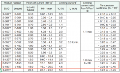
original E-153 is not available, so I want to choose E-183 as an alternative. Their characteristics differ as shown in the first attached picture.
2) Ferrite core:
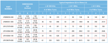
original LFB095051-000 is not available; want to substitute it with LFB143064-100; a bit different size, but quite similar impedence characteristics (see the second picture). I don't worry about the size, I think it will fit, but would I need to change the number of wire turns with the alternative?
I am good at building these nice things, but, unfortunately, not yet able to understand how they work, so your advice would be very much appreciated.
Thanks
Alvis
I have two questions on alternatives as original BOM items are not available at the moment.
1) Current Regulator Diodes D25, D75:
original E-153 is not available, so I want to choose E-183 as an alternative. Their characteristics differ as shown in the first attached picture.
2) Ferrite core:
original LFB095051-000 is not available; want to substitute it with LFB143064-100; a bit different size, but quite similar impedence characteristics (see the second picture). I don't worry about the size, I think it will fit, but would I need to change the number of wire turns with the alternative?
I am good at building these nice things, but, unfortunately, not yet able to understand how they work, so your advice would be very much appreciated.
Thanks
Alvis
Attachments
Have a look at posts #127, 128, 129 in this thread, for ideas about alternative ferrite cores. Wind as many turns as you are able to do comfortably, and be happy.
The PCB includes a footprint for the E-153 in both thru hole AND surface mount packages. My first preference would be to use the designer's chosen part (E-153) in surface mount
link to EU Mouser
My second choice would be to try the E-183 and hope for the best.
The PCB includes a footprint for the E-153 in both thru hole AND surface mount packages. My first preference would be to use the designer's chosen part (E-153) in surface mount
link to EU Mouser
My second choice would be to try the E-183 and hope for the best.
Oh! Thanks, Mark.
I have read all this thread, and saw the ferrite alternatives suggestions, but some of them are also not available 🙂 Clear now.
And I will definitely go with SMD E-153! Did not notice the pads! Nice!
-Alvis
I have read all this thread, and saw the ferrite alternatives suggestions, but some of them are also not available 🙂 Clear now.
And I will definitely go with SMD E-153! Did not notice the pads! Nice!
-Alvis
Mark, super simple question, I suppose, but just to be sure for the noob -
Do I understand correctly that R7 (820 ohms) it there just as a minimal resistance to not burn the LED, and if I do not want adjustable R2 as I know what LED and what fixed resistor I want with it, then I can put my resistor in R7 and jumper the R2. Correct?
-Alvis
Do I understand correctly that R7 (820 ohms) it there just as a minimal resistance to not burn the LED, and if I do not want adjustable R2 as I know what LED and what fixed resistor I want with it, then I can put my resistor in R7 and jumper the R2. Correct?
-Alvis
Just a build update. Its going slow and steady so far. My son did help a little bit but I still did most of the soldering. I like the Mega328 component tester. Its a little inaccurate with the inductors but otherwise pretty good. I have the power supply bits done and some of the resistors for each channel.

A couple of quick questions.
1. Is it best to use stranded or solid wire for L2?
2. Both the BOM's in thread show 100 ohm's for R30?R80 but board and schematic show 330 ohms. Just want to make sure before I solder.
Me
1. Is it best to use stranded or solid wire for L2?
2. Both the BOM's in thread show 100 ohm's for R30?R80 but board and schematic show 330 ohms. Just want to make sure before I solder.
Me
I have built Noirs with solid core insulated wire and with stranded insulated wire for L2. They worked equally well in my experience. Use what you've got.
R30 and R80 should be 330 ohms as shown on the PCB and the schematic. Although there's an excellent chance the HPA would work correctly with 100 ohms, 330 is the correct and preferred value. Feel free to try both and see whether you hear any difference.
R30 and R80 should be 330 ohms as shown on the PCB and the schematic. Although there's an excellent chance the HPA would work correctly with 100 ohms, 330 is the correct and preferred value. Feel free to try both and see whether you hear any difference.
- Home
- Amplifiers
- Headphone Systems
- Noir, a two transistor headphone amp: class-A, single ended, 150mA bias