Cliff, the UT601 does not measure inductance.
For that, you need the UT603 as I previously indicated.
For that, you need the UT603 as I previously indicated.
Thanks Galu.Cliff, the UT601 does not measure inductance.
For that, you need the UT603 as I previously indicated.
I should have had a closer look at its specs.
I'm currently working on buying a UT603 economically.
Thanks.Cliff, the UT601 does not measure inductance.
For that, you need the UT603 as I previously indicated.
I've placed the order.
Soon I'll be rubbing shoulders with the greats in terms of tools on hand. 🙂

Progress report.
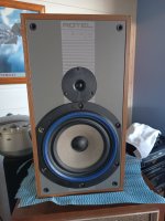
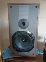
I've restored the Rotel RL870 crossover back to standard.
The parts I cut away for testing have been re soldered for the purpose of a driver comparison test.
The router wasn't suitable, but my jigsaw worked well.
After masking the baffle to protect it, I cut the woofer hole diameter on one of the boxes by approx 4mm to accommodate the B&W Woofer.
Being larger, the new woofers surround covers part of the Tweeters surround (ala Andrew Jones Elac).
I lightly chiselled the rebate to make the Tweeter flush with the baffle.
Finally I re stuffed the box with the original wadding (sealed box) and reassembled everything.
Now ready for a test.
Attachments
Thanks.Well done!
It certainly looks the part. Fingers crossed on how it sounds.
I'll wait until tomorrow to run them, but have a grandson over for a sleep night.
🙁🙂
If they perform OK, I'll then upgrade the other box & fit the new caps Ted gave me.
Finally, if there's an issue, I'll investigate replacing the Inductors.
There's slight water damage on the B&W paper cones.
They also appear to clash with the overall tones of the Rotels.
I thought painting them with a thin coating of Mod Podge should mask the water mark and tone down the color mis match.
I read on another thread that an application of Mod Podge changed the T/S parameters of a member's driver.
A less radical suggestion would be to mask off the cone and spray it lightly with matt black paint from an aerosol can.
A less radical suggestion would be to mask off the cone and spray it lightly with matt black paint from an aerosol can.
The amp I was using doesn't have balance, so it was the ear up against each speaker.Well done!
It certainly looks the part. Fingers crossed on how it sounds.
I asked my son (younger ears) to evaluate.
He said "original" was louder, but B&W upgrade was clearer and gave the impression it could handle more power.
Would does increasing the mH (Inductors) do to the sound?
I'll shortly be working on replacing the other driver & also replacing Caps with Teds.
The existing Caps are marked 3.3µF.
(WEGO ELKO 23VAC W Germany)
The cap in the XO I'm working on tests 3.9µF (presumably deterioration).
I was planning to replace them with Teds 2 x 2µF Caps, which read 3.940µF in parallel.
Is 3.940µF too far off the specified 3.3µF?
(WEGO ELKO 23VAC W Germany)
The cap in the XO I'm working on tests 3.9µF (presumably deterioration).
I was planning to replace them with Teds 2 x 2µF Caps, which read 3.940µF in parallel.
Is 3.940µF too far off the specified 3.3µF?
We can only guess....Would does increasing the mH (Inductors) do to the sound?
Pushes back the presence region,
reduces the contribution of the breakup region,
compensates the baffle step.
Thanks Allen.We can only guess....
Pushes back the presence region,
reduces the contribution of the breakup region,
compensates the baffle step.
What would that be/mean in layman's terms?
Less midrange.
The first thing you would need to do is learn how equalising changes things. Later on down the track you can discover the difference when that is also achieved by properly crossing out the driver issues and creating a good blend before equalising to taste.
Do you have access to an equaliser?
The first thing you would need to do is learn how equalising changes things. Later on down the track you can discover the difference when that is also achieved by properly crossing out the driver issues and creating a good blend before equalising to taste.
Do you have access to an equaliser?
In this case the aim is to compensate replacing an 8Ω impedence woofer with a 16Ω impedence woofer whilst keeping rollover similar.Less midrange.
The object being to maintain characteristics.
I see. Obviously what I said would happen if you changed only the inductor but what about the whole driver?
Obviously if you double the impedance you'd also want to double the inductance, the current one won't be large enough.. However the new driver may also be different than a simple doubling of impedance. Sensitivity could be different, the impedance curve character, the response and the breakup, for example.
Obviously if you double the impedance you'd also want to double the inductance, the current one won't be large enough.. However the new driver may also be different than a simple doubling of impedance. Sensitivity could be different, the impedance curve character, the response and the breakup, for example.
In my case it will end up being guess work.I see. Obviously what I said would happen if you changed only the inductor but what about the whole driver?
Obviously if you double the impedance you'd also want to double the inductance, the current one won't be large enough.. However the new driver may also be different than a simple doubling of impedance. Sensitivity could be different, the impedance curve character, the response and the breakup, for example.
Although a hobby, I have many pursuits.
I can't afford to accumulate all the tools needed to enable scientific analysis for my many hobbies.
I've invested in a quality tool to measure Inductance, Capacitance, & Resistance.
Beyond that it becomes a case of diminishing returns vs cost.
For this project it might involve tweaks based on known parameters.
At a guess I would start by doubling that inductor (after listening) and adjusting the tweeter resistor to get them to the same level. Then I'd adjust the woofer damping material to even out the bass. (Ok, I'd actually do more than that but I'm just trying to point out priorities.)
Thanks Allen.At a guess I would start by doubling that inductor (after listening) and adjusting the tweeter resistor to get them to the same level. Then I'd adjust the woofer damping material to even out the bass. (Ok, I'd actually do more than that but I'm just trying to point out priorities.)
The cabinets are filled with wool/cotton material.
Is this the dampening you're referring to?
Also, will the doubled Inductance cause the tweeters to brighten, then requiring Resistors to tame?
This existing XO also has an air core Inductor for the tweeter.
Does that assist in taming tweeter, and would this require doubling?
Yes.The cabinets are filled with wool/cotton material.
Is this the dampening you're referring to?
No, the doubling is just to keep up with the 16 ohms. If you go more or less it's up to you.Also, will the doubled Inductance cause the tweeters to brighten, then requiring Resistors to tame?
Second order filter. No you don't need to change it if you don't change the tweeter. It is air core for consistent high frequency behaviour with less distortion.This existing XO also has an air core Inductor for the tweeter.
Does that assist in taming tweeter, and would this require doubling?
Would does increasing the mH (Inductors) do to the sound?
You asked a couple of questions of me so here are my answers. There is no need to overthink things and AllenB's latest post is in accord with that philosophy.
Leaving the mH as is would increase the level of the midrange frequencies. As I said earlier, this may be no bad thing as evidenced by the fact that your son said "the B&W upgrade was clearer". If you both like the sound, then there is no need to change the iron-core inductor.
I was planning to replace them with Teds 2 x 2µF Caps, which read 3.940µF in parallel.
Is 3.940µF too far off the specified 3.3µF?
3.9 uF is around 18% higher than 3.3 uF, but should not produce a difference that can be detected by ear. Bear in mind that electrolytic capacitors can be 20% over in value and that you measured your current 3.3uF capacitor to be 4 uF anyway.
Note my Edits! Bit befuddled today!
Last edited:
- Home
- Loudspeakers
- Multi-Way
- No sound from one of the Rotel RL 870 Speakers?