What matters a great deal is bandwidth. For a single (ham) band the stages can be tuned / matched and that results in the highest gain / efficiency. Such "matched on chip" devices abound, like http://www.advancedsemiconductor.com/vimostm.html with some specs.
Some 40 years ago, sub-mW to a few hundred mW was possible with a single stage, like the 3N211 (now obsolete). I used that to bring the level of low noise VFO's to the level required by 23...27 dBm diode DBM.
Some RF (1-30 MHz) devices still can be found as replacement, http://www.advancedsemiconductor.com/transistors/rf_power_transistors.html and quite a few on eBay (including BJT). With the irreversible decline in RF broadcasting, more RF devices will become obsolete and probably within a decade, RF ham radio transmitters will be populated with (used in audio) tubes as they will stay.

89% of US "Boomers" tune into an AM radio at least once per day (compared to 73% of "GenZ"). A bit over 50% listen to AM radio between 2 and 4 hours per day.
But our new Volvo has no AM radio and you have to stream via iHeart and its mind-numbing commercials.
But our new Volvo has no AM radio and you have to stream via iHeart and its mind-numbing commercials.
@Aridace That advanced semiconductor IC looks sweet. I'm guessing they don't give those away (contact us for quote)
In summary-- it looks like you can do things to minimize the number of stages but ultimately "ya gonna have a few," especially as power ramps up.
@jackinnj just the name iHeart is mind-numbing
In summary-- it looks like you can do things to minimize the number of stages but ultimately "ya gonna have a few," especially as power ramps up.
@jackinnj just the name iHeart is mind-numbing
In the border region Panama - Costa Rica, portable radios can only receive 1 station and it's active between 15.00 and 18.30 Z. More stations can be heard when using an external antenna but the closest one is at ~100 Km with a power of ~ 1KW. So for car radios with old fashioned "whip connected to input LC" the useful distance is ~30 Km. With active whip the radius for good reception can be up to thrice of that but unless in a rural area, it's limited by EMI. As the region is very hilly and forested, FM reception with standard receiver in a car is more than a nuisance.
@Aridace That advanced semiconductor IC looks sweet. I'm guessing they don't give those away (contact us for quote)
In summary-- it looks like you can do things to minimize the number of stages but ultimately "ya gonna have a few," especially as power ramps up.
---
Already in the mid 1970s Motorola produced VHF amplifier modules. They were reliable and ham radio operators even used those starting at 175 MHz for use on 144-146 MHz. I too used one in my DIY FM TX. If you can use such a module it'll outperform any discrete setup so it's worthwhile spending time to search the most suitable one. These modules are also used for emergency services (police,1st aid etc.) so have to be very reliable.
Giving away (sample) won't work because the firm is a reseller.
Nice example (shop sells a lot of RF / VHF goodies)
https://www.rf-microwave.com/en/motorola/mhw613a/vhf-power-amplifier-module/mhw613a/
https://www.rf-microwave.com/en/motorola/mhw613a/vhf-power-amplifier-module/mhw613a/
My current interest is solid state heating in the 900MHz range (microwave pyrolysis). I have seen research using a single mode cylindrical cavity resonator that could achieve pyrolysis of rice husks within ten seconds at about 40W. Very low power, high efficiency, in other words. At the higher end of the power range most of the small scale research is around the 750 watt area. In trying to piece together what something similar might look like, this is one scenario I have come up with at the high end of the power range, including source generation:
Any thoughts?

Any thoughts?
The setup (VCO, amp and power amp module) provides the power required but unless optimum parameters are known, would require some experimentation. Is the goal, reliable production of graphene from biomass?
I'm assuming you mean the optimum parameters inside the resonator?
Yes on the biomass. I'm looking mainly at bio oils, with biochar and gasses as secondary and tertiary. Phenol extraction from pyrolyzed soft wood looks very interesting. Phenol then being converted to thermosetting resin for instance. I can link you some papers if you're interested. Here is some supplementary material for the single mode resonator experiments. https://www.rsc.org/suppdata/c9/gc/c9gc02745a/c9gc02745a1.pdf
Yes on the biomass. I'm looking mainly at bio oils, with biochar and gasses as secondary and tertiary. Phenol extraction from pyrolyzed soft wood looks very interesting. Phenol then being converted to thermosetting resin for instance. I can link you some papers if you're interested. Here is some supplementary material for the single mode resonator experiments. https://www.rsc.org/suppdata/c9/gc/c9gc02745a/c9gc02745a1.pdf
It looks like a well researched process, especially because of the variety of available suitable organic material that even could include non-chlorinated plastics. Parameters inside the cavity indeed are an issue but maintaining resonance looks to have been solved for several materials so isn't an issue either. Provided the proper material (corrosion) for the resonator, RF pyrolysis might be a good tool for recycling of stuff that with conventional means can't be recycled. Temperature control could be used to prioritize certain products. Interesting project!
Yes, the applications are numerous. Pyrolysis is an amazing process and you can turn pretty much anything into energy dense coal-like products. "Wet Pyrolysis" is another good technique worth taking a look at. IIRC it does well with waste plastics. Solid state heating seems like it might have a bright future as at a bare minimum it will vastly improve the cooking capabilities of the conventional microwave oven; almost to a Jetsons level where you can you can 'TV Dinner' entire meals but for real. It's already being done at the professional level and you can get a chef-grade unit for about 8000$. Of course we audio DIYers aren't afraid to look under the hood 😉
Relating to the Huber+Suhner modules in the above video, it dawned on me to show this project. It's a mini-ITX quad core with icepower modules and multiple DC/DC converters. I was inspired by the newer Jeff Rowland monolith slab style amps. Now getting into RF stuff I can see where Mr. Rowland got his inspiration from. Even better for me because I know how to make RF tight enclosures entirely by accident...thanks Jeff lol!

Long ago I was involved in analyzing the effect of fluoridated hydrocarbons (from spray cans) on smoking and back then, RF pyrolysis could have simplified the procedure considerably. The advantage of this kind of RF heating is enough to make traditional uwave ovens obsolete rapidly.
Looking under the hood (and measuring) indeed is a good way to learn. It also provides a good learning curve for circuit simulation that when constructed, will behave as simulated 😉
Looking under the hood (and measuring) indeed is a good way to learn. It also provides a good learning curve for circuit simulation that when constructed, will behave as simulated 😉
This thread sprang to life about 6 years ago. Back in post #7 I talked about designing my own ham radio. A couple months ago a friend in Florida asked me if I could help him make a power amp for his new Hermes Lite 2 SDR which put out about 5 watts. I have a Yeasu FT817 which puts out 5 watts, so I went for it.
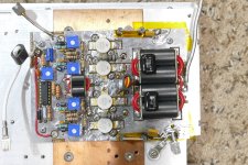
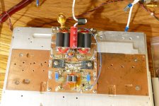
I remembered buying a bunch of scrap MRI amplifier boards from 1999 and 2000 at the Dayton Hamfest back in 2011 mostly for the heat sinks. I had stuffed the remains into a box which has been in an abandoned modular home ever since. I found the box which yielded a collection of large RF transistors. One board had 14 MRF150 transistors on it. A little Googling said that I had hit the jackpot. There was a Motorola paper detailing the design of an amplifier that could get 600 watts from four of these devices in PPP from 5 watts of RF drive and cover 1.8 to 30 MHz. What was even more surprising was that the company that was mentioned as a source of parts in this 30 year old App Note was stillaround and still had the PCB and parts for it. I got the board and parts, less the MRF150 transistors for about $75 shipped. Does it work?
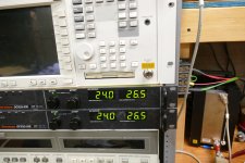
Here is a picture of my new creation. Note the 1999 date codes on the transistors. Note the power meter needle pointing to .675 on the 100 mW scale. There is a 40 dB attenuator in front of the power meter sensor so this is now a zero to 1000 watt scale, corresponding to 675 watts. I have a pair of Sorrensen power supplies wired in series to run this beast. I had to run a new dedicated line to the breaker box to feed them. Each supply is set for 24 volts, so this amp eats 26.5 amps on 48 volts or 1272 watts for an efficiency of 53% and this is near saturation. The efficiency is lower if I keep the amplifier in the 500 to 550 watt range for linearity. I'm currently looking into some newer LDMOS parts that get efficiencies in the high 70's.
I am using a two stage a broadband amp from QRP labs to drive this thing. It will turn the HP sig gen output into 10 watts.
I remembered buying a bunch of scrap MRI amplifier boards from 1999 and 2000 at the Dayton Hamfest back in 2011 mostly for the heat sinks. I had stuffed the remains into a box which has been in an abandoned modular home ever since. I found the box which yielded a collection of large RF transistors. One board had 14 MRF150 transistors on it. A little Googling said that I had hit the jackpot. There was a Motorola paper detailing the design of an amplifier that could get 600 watts from four of these devices in PPP from 5 watts of RF drive and cover 1.8 to 30 MHz. What was even more surprising was that the company that was mentioned as a source of parts in this 30 year old App Note was stillaround and still had the PCB and parts for it. I got the board and parts, less the MRF150 transistors for about $75 shipped. Does it work?
Here is a picture of my new creation. Note the 1999 date codes on the transistors. Note the power meter needle pointing to .675 on the 100 mW scale. There is a 40 dB attenuator in front of the power meter sensor so this is now a zero to 1000 watt scale, corresponding to 675 watts. I have a pair of Sorrensen power supplies wired in series to run this beast. I had to run a new dedicated line to the breaker box to feed them. Each supply is set for 24 volts, so this amp eats 26.5 amps on 48 volts or 1272 watts for an efficiency of 53% and this is near saturation. The efficiency is lower if I keep the amplifier in the 500 to 550 watt range for linearity. I'm currently looking into some newer LDMOS parts that get efficiencies in the high 70's.
I am using a two stage a broadband amp from QRP labs to drive this thing. It will turn the HP sig gen output into 10 watts.
Attachments

I was working on an all band communications receiver, using an extra QRP Labs VFO to seamlessly switch the prototype bandpass filters as the VFO tunes, and it worked well as the VFO firmware allows the switch points to be user programmed. The only thing remarkable is that I learned the band select lines on the VFO provide a low output rather than a high when engaged, so I had to add some transistor switches to the board to route 5 volts to the selected filter. This part of the VFO does not seem to be documented for use with non QRP Labs filter boards.
Then I carelessly hooked the VFO unit up to 12 VDC and smoked it.
So right now I am ( maybe) working on a simple DC receiver to listen to the local SSB nets. It will be at least 75 meters, and probably 40, although there is only a bandpass filter for 75 on the board right now. I thought I would use a 3 pin header and jumper to switch between two filters to the input.
The detector is a SA602. This board shows the scars of a fair amount of trial and error. Besides the single filter and detector, there is a simple audio amp and a couple of voltage regulators on the board. At one point I was taking balanced audio from the SA602 but I found I could not tell any difference between balanced and single ended, so I stripped all the balanced stuff out.
Progress is glacial. I'm not sure what I am going to use for an LO if this ever makes it to completion. Right now I am using the FeelTech FY6600 function generator.
Win W5JAG
Attachments
Last edited:
Oh crap! I'm so sorry!Then I carelessly hooked the VFO unit up to 12 VDC and smoked it.
How is the LO tuned?
That "design my own ham radio" project has been simmering in the back of my mind for far too long. Now if I can only put up some type of antenna, I may have the necessary motivation to get past the "thinking about it" stage.
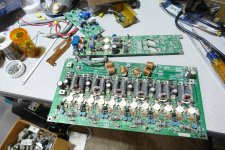
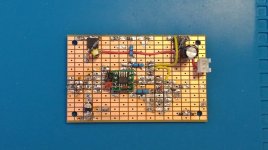
Before the heat sink from the 600+ watt test run was cool I dreamed up an idea for my own version of that 600 watt amp with some of those newer LDMOS parts. I threw together a simple PCB layout and knocked out a quick and (very) dirty prototype board, ordered some parts and built one. The first test ended when I discovered that the board has a case of SPS (smoking parts syndrome) but at least it didn't just blow up. The power output was only 150 watts, so something is not right. Most of the parts values that I put on the board were just SWAGs that were based on the MRF150 board. MRF150's are not LDMOS so their impedances are likely quite different than what's in the board now, which are some unknown "disposable" pulls with house numbers on them from an MRI amp. They didn't explode, so I can put in the correct LDMOS fets. Note that I'm using two 0 to 33 volt bench supplies wired in series with a total current capability of 33 amps. Parts DO EXPLODE when things go wrong. I will be away from my lab for one to two weeks, so no further work will get done for a while.
Before the heat sink from the 600+ watt test run was cool I dreamed up an idea for my own version of that 600 watt amp with some of those newer LDMOS parts. I threw together a simple PCB layout and knocked out a quick and (very) dirty prototype board, ordered some parts and built one. The first test ended when I discovered that the board has a case of SPS (smoking parts syndrome) but at least it didn't just blow up. The power output was only 150 watts, so something is not right. Most of the parts values that I put on the board were just SWAGs that were based on the MRF150 board. MRF150's are not LDMOS so their impedances are likely quite different than what's in the board now, which are some unknown "disposable" pulls with house numbers on them from an MRI amp. They didn't explode, so I can put in the correct LDMOS fets. Note that I'm using two 0 to 33 volt bench supplies wired in series with a total current capability of 33 amps. Parts DO EXPLODE when things go wrong. I will be away from my lab for one to two weeks, so no further work will get done for a while.
Attachments
- Home
- Member Areas
- The Lounge
- No RF gear here?