... Clearly no existing noise blanker could eliminate that. Either I have to design a new radio with a ~ 1 MHz wide IF and noise blanker able to handle the ~450 uS pulse repetition rate, or to construct a different wideband directional antenna ....
Are you familiar with the Collins 136B-2 blanker? It is a low VHF TRF sub receiver, whose only function is to receive noise pulses and convert them to a control voltage without compromising the IF of the main receiver.
http://www.jptronics.org/Collins/136B/collins.136b.pdf
I have one installed in my KWM-2, although I don't recall ever using it since ignition noise is a thing of the past.
The 136B-2 is obsolete, but the concept might not be.
I didn't know the circuit but one look was enough to know that a pulse repetition frequency of 2.2 KHz won't be handled by it. No existing blanker handles that because they are retriggered, resulting in a ~6ms blanking pulse. That still might be OK for CW but for modes like AM, SSB the blanker needs to produce a blanking pulse down to 10 us wide and repeat that within 450 us.
there was an excellent noise blanker by DJ7VY
I can't find the original article from CQ-DL, maybe UKW-Berichte/VHF communications,
but secondary literature:
< Storaustaster >
< https://worldradiohistory.com/Archive-DX/Ham Radio/80s/Ham-Radio-198006.pdf >
(where U. Rohde cites him: cq-dl 1978 july, page 300)
< home >
I can help with translations.
Cheers, Gerhard
I remember an even better article on blankers in Ham Radio, long ago. Instead of switching off the IF signal, a LO is gated. The advantage is obvious: because the LO signal is large, there's little or no issue with balance, voltage spikes and intercept point. If the phased active dipoles don't provide enough suppression, the RX to be built will have a ~60 MHz, 1MHz wide 1st IF. It will feed a fast blanker and the output will be used for a gated LO for the 2nd (properly delayed) IF, probably 10.7 MHz. 3rd IF, 455 KHz as that results in closer to ideal demodulators, notch filters etc. The start for the gated LO already has been made: 27 MHz CB crystals, at fundamental frequency, can be pulled over 20 KHz. A 10 MHz XTO, mixer and some filtering provide 1000-1020 KHz and using that with a PLL, VCO at 50 MHz, delivers a very clean signal for the gated LO.
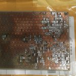
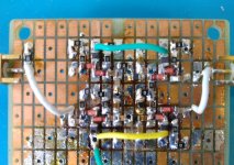
Putting a piece of copper foil over a piece of perf board to make a ground plane looks like an interesting and useful construction technique.
Yes. But you can buy perf board with a ground layer, there is not much of a
price difference. There is even better board with plated-through holes, you do
not lose the square pads on the other side so easily.
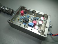
(My implementation of Scott Wurcers' mic preamplifier.)
price difference. There is even better board with plated-through holes, you do
not lose the square pads on the other side so easily.
(My implementation of Scott Wurcers' mic preamplifier.)
Attachments
Last edited:
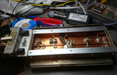
I hate to think what that machined box cost ...
I lost a LOT of the square pads off that first prototype board when I was making the switch to SMD and didn't know what I was doing, but after gaining some experience, I have gotten to where I can work / rework them pretty extensively and I don't think I have lost a pad since. These boards are not plated through.
I've been cleaning off that first board in my spare time, and it looks really bad - I have probably lost 4-5% of the pads off of it, and in some places there is a big area that is just destroyed and unusable.
Another SG-9 IF board has landed here at W5JAG. I haven't had a chance to strip it down and test it for function yet. It is supposed to be a pull from a working radio, but everything works until it doesn't so I expect repairs will be necessary.
Not sure what I want to do with it. Probably clean it up, repair it, and put it in inventory.
Attachments
For those interested in propagation:
Space Weather Message Code: WARK06
Serial Number: 446
Issue Time: 2021 Sep 17 2345 UTC
EXTENDED WARNING: Geomagnetic K-Index of 6 expected
Extension to Serial Number: 445
Valid From: 2021 Sep 17 2025 UTC
Now Valid Until: 2021 Sep 18 0600 UTC
Warning Condition: Onset
NOAA Space Weather Scale descriptions can be found at
NOAA Space Weather Scales | NOAA / NWS Space Weather Prediction Center
Potential Impacts: Area of impact primarily poleward of 55 degrees Geomagnetic Latitude.
Induced Currents - Power grid fluctuations can occur. High-latitude power systems may experience voltage alarms.
Spacecraft - Satellite orientation irregularities may occur; increased drag on low Earth-orbit satellites is possible.
Radio - HF (high frequency) radio propagation can fade at higher latitudes.
Aurora - Aurora may be seen as low as New York to Wisconsin to Washington state.
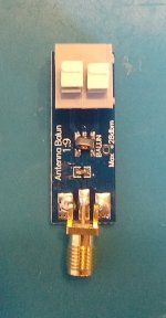
I got one of the super cheap 9:1 balun boards from AliExpress and it seems to help with the mismatch between the high impedance wire and low impedance antenna input, and, while I haven't played with it much, it does seem to work.
Very weak MW broadcast stations that would barely deflect the AGC meter without the balun, move up to a 1 or a little higher with it. These complete boards are less than the cost of a surplus transformer, so I'll probably get a few more.
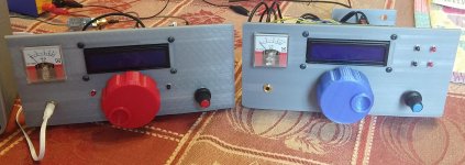
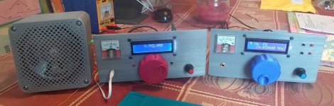
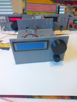
I moved the SSB transceiver to a smaller breadboard to cosmetically sort of match the receiver. Both are 190 x 190 mm now. The broadcast receiver is mostly empty space, but the transceiver is a bit crowded. I'm out of shielded cable, so I could not hook up the mic input, and I'm still considering putting a mic gain control in the spot where the mic receptacle is ( not enough knobs ). It's pretty tight, but I think I can fit a pot in there. I didn't have any shorting 3.5mm jacks either, so the CW key is also not wired, yet. Finally, I have a bulkhead SMA antenna connector, but apparently it uses 2.5M hardware instead of 3M, so no antenna jack yet, either ...
The SSB rig was printed on the big printer at the office, and has a slightly deeper VFO knob to work around the long shaft on the encoder and save me the trouble of changing it out for a shorter shaft. I don't like that printer - I prefer the cheap box of parts printer. The receiver was printed on the box of parts.
The LCD displays don't match well at all - it's a lot worse than the picture shows even after a not insignificant amount of time being spent trying to match them. In fact it's just unacceptable even by my standards; the display on the receiver will have to be changed out. The SSB rig was on the old breadboard on the desk in my office, and the receiver is here, so this is the first time they have been side by side to see the mismatch.
The receiver gets heavy use when I am here at the second house ( listening to it right now ) , and the transceiver is used daily for receiving ( at least ) at my office, and both still seem to be trouble free and satisfactory for their respective purposes. I'll probably leave the transceiver here for a while since they sort of make a set, now.
So long Chief Wahoo - hate to see you go.
Very weak MW broadcast stations that would barely deflect the AGC meter without the balun, move up to a 1 or a little higher with it. These complete boards are less than the cost of a surplus transformer, so I'll probably get a few more.
I moved the SSB transceiver to a smaller breadboard to cosmetically sort of match the receiver. Both are 190 x 190 mm now. The broadcast receiver is mostly empty space, but the transceiver is a bit crowded. I'm out of shielded cable, so I could not hook up the mic input, and I'm still considering putting a mic gain control in the spot where the mic receptacle is ( not enough knobs ). It's pretty tight, but I think I can fit a pot in there. I didn't have any shorting 3.5mm jacks either, so the CW key is also not wired, yet. Finally, I have a bulkhead SMA antenna connector, but apparently it uses 2.5M hardware instead of 3M, so no antenna jack yet, either ...
The SSB rig was printed on the big printer at the office, and has a slightly deeper VFO knob to work around the long shaft on the encoder and save me the trouble of changing it out for a shorter shaft. I don't like that printer - I prefer the cheap box of parts printer. The receiver was printed on the box of parts.
The LCD displays don't match well at all - it's a lot worse than the picture shows even after a not insignificant amount of time being spent trying to match them. In fact it's just unacceptable even by my standards; the display on the receiver will have to be changed out. The SSB rig was on the old breadboard on the desk in my office, and the receiver is here, so this is the first time they have been side by side to see the mismatch.
The receiver gets heavy use when I am here at the second house ( listening to it right now ) , and the transceiver is used daily for receiving ( at least ) at my office, and both still seem to be trouble free and satisfactory for their respective purposes. I'll probably leave the transceiver here for a while since they sort of make a set, now.
So long Chief Wahoo - hate to see you go.
Attachments
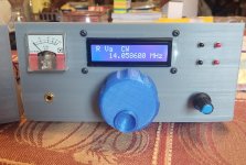
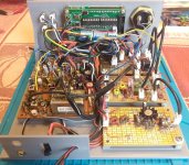
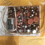
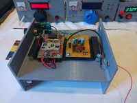
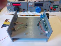
I finally got around to finishing out the simple FM tuner put together about five years ago, mostly to try out a marginally improved method of printing 3d chassis for simple projects.
I’ve always liked the LMB-Heeger CO series of cabinets, and keep a few in stock, but over the years they have really grown expensive. So this represents a first attempt at a 3D printed facsimile of that cabinet / chassis style. I haven’t printed out a wrap around cabinet for this chassis yet, but it should present no difficulty. There are a bunch of extra holes for things not yet installed - like an on / off switch ...
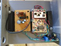
The chassis was printed out for the perfboard version of the receiver, but after using that for a week or two, I decided to rebuild the RF part unto one of the SMD protoboards, deleting one of the two MuRata ceramic filters from the original and also deleting the IF amplifier between the tuner and CA3089 chip. Instead of printing a new chassis, I just printed an adapter to carry the new boards and allow mounting to the existing supports.
Audio output from the FM chip goes to a cheap store bought LM386 amplifier board, that has had the cheap generic chip replaced with a genuine 80's vintage LM386-4. The purpose of this receiver is for reception of the local sports team broadcasts on the FM band, and this simple tuner is satisfactory for this purpose. It's sensitive and selective, but the audio would be better with a better amp.
The diffuser for the frequency counter display was made from semi translucent blue filament, printed very thin (1 mm) and with minimal infill (10%), so that the diffuser remains translucent. It is sized to be held in place by a press fit, with a thin bead of glue around the edge for good measure.
I cut the stereo decoder circuit away from the old tuner perfboard for future use. I don’t see anything to be gained by rebuilding it in SMD. It’s not in circuit right now; just attached to the chassis so I won’t misplace it. The top half of the chassis remains open to hold better audio amplifiers. Stereo and better amps are a low priority right now.
I’ve always liked the LMB-Heeger CO series of cabinets, and keep a few in stock, but over the years they have really grown expensive. So this represents a first attempt at a 3D printed facsimile of that cabinet / chassis style. I haven’t printed out a wrap around cabinet for this chassis yet, but it should present no difficulty. There are a bunch of extra holes for things not yet installed - like an on / off switch ...
The chassis was printed out for the perfboard version of the receiver, but after using that for a week or two, I decided to rebuild the RF part unto one of the SMD protoboards, deleting one of the two MuRata ceramic filters from the original and also deleting the IF amplifier between the tuner and CA3089 chip. Instead of printing a new chassis, I just printed an adapter to carry the new boards and allow mounting to the existing supports.
Audio output from the FM chip goes to a cheap store bought LM386 amplifier board, that has had the cheap generic chip replaced with a genuine 80's vintage LM386-4. The purpose of this receiver is for reception of the local sports team broadcasts on the FM band, and this simple tuner is satisfactory for this purpose. It's sensitive and selective, but the audio would be better with a better amp.
The diffuser for the frequency counter display was made from semi translucent blue filament, printed very thin (1 mm) and with minimal infill (10%), so that the diffuser remains translucent. It is sized to be held in place by a press fit, with a thin bead of glue around the edge for good measure.
I cut the stereo decoder circuit away from the old tuner perfboard for future use. I don’t see anything to be gained by rebuilding it in SMD. It’s not in circuit right now; just attached to the chassis so I won’t misplace it. The top half of the chassis remains open to hold better audio amplifiers. Stereo and better amps are a low priority right now.
Attachments

......
1N4007 is said to be a PIN diode. The smaller members of the family are not.
.....
I'm working on switched bandpass filters (50 ohm shunt first, third order) to cover the 0 - 30 MHz HF range, and I was thinking of trying to switch them with 1N4148 general purpose diodes instead of relays. I have a bunch of SMD 1N4007 diodes. Would 1N4007 be a better choice than 1N4148?
Try it, and see?
After a year of using the general coverage broadcast receiver, I've decided to leave it alone. It does what it is supposed to do really well.
Win W5JAG
Neither one are PIN diodes. You can “try it and see”, but I doubt you’ll get very far with them as RF switches.
1N4001 to 1N4006 are not. 1N4007 is. The only one in the family.
Nearly no PIN diode works below ~2 MHz because of carrier lifetime.
You cannot simulate it in Spice. 1N4007 is a power diode and as such
may have relatively large capacitance. Maybe with a lot of backward voltage.
I used HSMP-3864 as attenuator on 432 MHz, BAR64-5 as switch
in my 432MHz transverter. The attenuator has abt. 2-45 dB range,
virtually no IMD.
Attachments
Last edited:
I forgot I have some BAR64-03W. I got those to use as attenuators, but the (may or may not be PIN) diode attenuator in the broadcast receiver is working satisfactory - didn't need them; the receiver has never exhibited any evidence of overload.
I can try those if the 1N4148 are unsatisfactory.
HSMP 3864 did not return any results in the Mouser search engine.
Win W5JAG
I can try those if the 1N4148 are unsatisfactory.
HSMP 3864 did not return any results in the Mouser search engine.
Win W5JAG
Last edited:
The HSMP-3864 is an old HP / Avago part. It is extinct now.I forgot I have some BAR64-03W. I got those to use as attenuators, but the (may or may not be PIN) diode attenuator in the broadcast receiver is working satisfactory - didn't need them; the receiver has never exhibited any evidence of overload.
I can try those if the 1N4148 are unsatisfactory.
HSMP 3864 did not return any results in the Mouser search engine.
Win W5JAG
Attachments
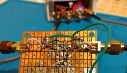
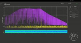
This is a 3 pole low pass with the cutoff supposed to be 2.5 MHz, but it came out a little high. These are super cheap parts of dubious tolerance. A strip of 50 inductors were less than $1 USD, and the capacitors are similar "quality".
The switches are 1N4148 because of the carrier lifetime issue at low frequency, in a back-to-back arrangement. The diodes are terminated with 1K resistors, and I used 100 nF blocking capacitors, and good quality 1 mH RF chokes in the DC line. I have some 1N4148 in SOD-323 package, but of course I forget to bring them. The RP can't detect anything going through the filter when it is switched off. I've swept it with and without the diode switching and I can't tell any difference in the frequency response. The unswitched filter next to the low pass, is supposed to be a 2-6 MHz bandpass, but it also sweeps a little high - it's more like 2.75 -6.75 MHz.
The new Red Pitaya firmware has some really good additional features. The signal generators can sweep a defined range, and a log display on the X axis can be selected. Just letting the RP sweep a frequency range, and using the max hold on the analyzer will, over the course of a few minutes, give a usable display of the bandpass.
Pics are the filter, and the response to about 29 MHz , log scale on frequency.
Win W5JAG
Attachments
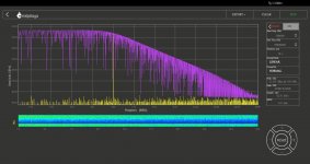
And the bandpass filter. Before I installed the switches, I swept it using the linear frequency scale and saw some ripple, but it looked insignificant. It is a lot more pronounced looking at it on a log scale.
Win W5JAG
Win W5JAG
Attachments
FWIW, there's a Collins 851S1 receiver up for auction at Schulman Auctions -- a rare bird.Are you familiar with the Collins 136B-2 blanker? It is a low VHF TRF sub receiver, whose only function is to receive noise pulses and convert them to a control voltage without compromising the IF of the main receiver.
- Home
- Member Areas
- The Lounge
- No RF gear here?