Every RF gain stage has two important specs associated with it. The actual stage gain and its maximum undistorted output power. Both change as the RF frequency is changed. Say a given part shows a gain of 10 dB at 100 MHz and a P1dB point of +10 dbm. This part will amplify an RF signal at 100 MHz by 10 dB up until you drive it hard enough get +10 dbm (10 milliwatts) out of it, at this point its gain has dropped to 9 dB. The P1db point is the output power level where the gain drops by 1 db. This is the beginning of the point where the part begins to saturate and can't produce much more power no matter how hard you drive it.In reading about how gain vs power works I am getting tripped up on the practical aspects of how this is implemented. For example, if you start with a low power signal, say 10mW, and you reach a final output of 10W, how many interim stages are usually needed? What if the power is stepped up to 100W, will that require every stage up to and including the 10W stage? Or can you go from 10mW to 10W, or 100W, or 1000W in just a couple of stages from the 10mW input signal?
To get 10 watts from a 10 mW signal requires 30 dB of total gain and a P1db point that is higher than 10 watts. The actual number of stages to do this isn't fixed. There are devices that have 20 db of gain and a P1db point higher than 1 watt which will take your 10mW signal up to 1 watt. You would then need a stage with 10 db of gain and a p1db greater than 10 watts.
At most frequencies below 1 GHz it is usually possible to find single stage amps with at least 10 B of gain. At frequencies below 100 MHz single stages with gains of over 20 dB are possible. The board shown in post #875 can produce 500 or more watts from 5 watts of input power. This is a gain of 20 dB and a P1dB of 500 watts.
At higher RF frequencies stages tend to have less gain.
My current test station for these RF power amps allows me to adjust the supply voltage from zero to 66 volts and limit the current to any value from zero to 33 amps. I also have full control over the RF drive level and frequency from 100 KHz to 3 GHz.

Oh crap! I'm so sorry!
How is the LO tuned?
A PIC reads an encoder and controls an Si5351 frequency synthesizer chip.
Win W5JAG
Quite a few options, I can (probably will) just buy another of the VFO kits. I have a spare actual DDS board of the type used in the SSB transceiver, and it can bandswitch, but its switch points are fixed in the firmware and not optimal for my bandpass filters.
I think I have all the parts to build a simple one using an Arduino and an Si5351 board. I've sorta been meaning to get around to trying this. I've just had higher priority stuff to do for the last few months.
An LC oscillator is probably fine at such low frequencies. I likely have a few decades old examples pre built somewhere in my junk box.
Win W5JAG
lol!
Yeah ... time!
I buy kits where possible these days, sometimes modifying them slightly. There simply isn't enough time to design what you need exactly. It's also a lot less expensive if you value your time.
Yeah ... time!
I buy kits where possible these days, sometimes modifying them slightly. There simply isn't enough time to design what you need exactly. It's also a lot less expensive if you value your time.
You guys probably already know this, but Fair Radio is in the process of closing down. I still remember looking forward to the catalogs with the Dymo tape labels on the merchandise.
https://fairradio.com/
https://fairradio.com/
Yes, thanks.
I wish I had had an opportunity to visit a few decades ago. Today I'm in the "lightening my life" phase. Gun collection is gone, working on old radios and other things. Sorting unfinished projects.
I wish I had had an opportunity to visit a few decades ago. Today I'm in the "lightening my life" phase. Gun collection is gone, working on old radios and other things. Sorting unfinished projects.
The "10 watt HF amp" board that I use to get 10 watts of drive from a 100 milliwatt signal generator came from QRP labs. My friend got his kit in a few days but mine took almost two weeks and was shipped from Turkey. According to their web site QRP labs is in the UK.
I have always avoided a trip to Fair Radio, Mendelsons, or Parts Express because I know what would happen. I am also in another "stuff reduction" phase of my life as I realize that I couldn't possibly finish all the partially complete projects that I have already.
I have always avoided a trip to Fair Radio, Mendelsons, or Parts Express because I know what would happen. I am also in another "stuff reduction" phase of my life as I realize that I couldn't possibly finish all the partially complete projects that I have already.
I've been to the Lima store twice. Back when I had the opportunities to get away to Dayton, If I could , I left a day or two early so I could go up to Fair and not be pushed for time.
Win W5JAG
Win W5JAG
I have to thank all the ambitious Radio Amateurs who did EME (Earth Moon Earth):
When I was doing Technical Support of Spectrum Analyzers, EME gave me the best illustration of the difference between Most spectrum analyzers, Versus Real Time spectrum analyzers.
Non Real Time spectrum analysis and Non Real Time EME:
Say "Hello, Test, 1, 2, 3" into the EME microphone of an EME transmitter.
About 2.5 seconds later, you hear from the EME receiver: "Hello, Test, . . . . . . . 3).
The missing 'data' (1, 2,) is because it is not real time.
The 2.5 second delay has nothing to do with real time versus non real time.
Real Time spectrum analysis and Real Time EME:
Say "Hello, Test, 1, 2, 3" into the EME microphone of an EME transmitter.
About 2.5 seconds later, you hear from the EME receiver: "Hello, Test, 1, 2, 3).
There is No missing 'data' because it is in real time mode.
The 2.5 second delay has nothing to do with real time versus non real time.
Real Time spectrum analysis does not miss a spectral event (within the bandwidth of the real time spectrum setting).
Thanks Again!
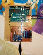
Over the weekend I put together a test jig to tinker with the Si5351 frequency synthesizer chip, or the Arduino, or maybe both - I've had the Arduino for six or seven years and never used it except to make the LED flash.
The QRP Labs Si5351 based VFO, and the DDS VFO used in the SSB transceiver, are well developed products at reasonable prices, so I don't anticipate, or even plan on trying, to come up with anything that would be a viable replacement for either.
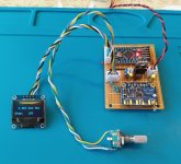
Anyway, the clock 0 output seems to work although I have not hooked up an encoder yet. The 128 x 64 OLED display is ridiculously small (slightly less than an inch), but surprisingly easier to read than I would have anticipated. Second pic is received signal strength across the kitchen table on the broadcast receiver, using an ordinary test clip as an antenna for the Si5351, and the outdoor fifty foot wire antenna for the BC rcvr .
Win W5JAG
The QRP Labs Si5351 based VFO, and the DDS VFO used in the SSB transceiver, are well developed products at reasonable prices, so I don't anticipate, or even plan on trying, to come up with anything that would be a viable replacement for either.
Anyway, the clock 0 output seems to work although I have not hooked up an encoder yet. The 128 x 64 OLED display is ridiculously small (slightly less than an inch), but surprisingly easier to read than I would have anticipated. Second pic is received signal strength across the kitchen table on the broadcast receiver, using an ordinary test clip as an antenna for the Si5351, and the outdoor fifty foot wire antenna for the BC rcvr .
Win W5JAG
Attachments

Revision 2 with a Pro Mini in place of the Uno, but otherwise completely unremarkable. I damaged the OLED display with my hot air gun removing it from the first PCB, and I thought that it would for sure be kaput, but the parts of the display I am using still seem to work fine.
Win W5JAG
Win W5JAG
Attachments
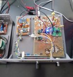
The SA602 product detector board / receiver was working okay, but here is revision 2 of the direct conversion (“DC” for the non hams) receiver; this variant using the AD831 mixer chip as the product detector. I thought this chip was interesting back when I was working on the SSB transceiver, but it wasn’t suitable for that project and I haven’t had a chance to use it since then, hence the use here.
The goals for this receiver are modest - I want something to have here at the lake house for comfortable loudspeaker listening to the local four state (AR, KS, MO, and OK) area 75 meter SSB nets, and CW on the low end of 80 later in the evenings. It is a kitchen table receiver, so comfortable listening means being able to hear it anywhere in the top floor of the house. For an antenna, it gets to use the same end fed wire the broadcast receiver uses.
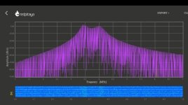
The front end is the ordinary double tuned, top coupled, bandpass filter. This one is pretty badly over coupled at present, as seen by the double peaks on the Red Pitaya FFT. I actually haven’t tuned it at all - the FFT is the "as wound" bandpass response; eventually I’ll get around to optimizing it, but it’s a low priority right now.
The AD831 evaluation board has had the 10 nF ceramic output cap removed and a 2.2 uF electrolytic substituted to make it more suitable as a product detector, but is otherwise unchanged. It is set for 10 dB conversion gain.
In between the filter and the AD831 is a Mini Circuits MAR-6+ MMIC as an RF amp which should be at least 22 dB gain, making the total RF gain 32 dB.
At present the AF portion is just a 741 op amp (30 dB) and an LM-386 (46 dB) making the overall gain 108 dB end to end. The two IC’s are of the 10 for $1 USD variety from AliExpress that, surprisingly, seem to work exactly like they are supposed to work. They are in sockets so they can be easily changed to better parts if this version turns out to be a keeper.
Everything runs off the same 10 volts the AD831 requires. I swapped out that insanely small OLED display for a 1602 LCD that is driven by one of the generic I2C convertor boards, but when get to the point that I need to print a dedicated chassis, I might go back to the OLED.
It is built on the first SMD board I used, that is really rough looking and missing a lot of pads, but on the good side the AD831 board covers up the worst looking part, and there is a lot of available room left for improvements. There is room on the top part of the board for more bandpass filters and an on board Raduino VFO, and on the bottom side there is enough room to make it into a simple superhet when I come to my senses and get tired of DC.
Next up is narrowing the audio channel bandwidth to a communications width, and then adding some sort of audio leveling so the guys on the other side of the state are more or less the same audio level as the guys in the immediate local area.
Other than the unrestricted audio bandwidth and unleveled volume from the output, it doesn’t work half bad. It is plenty sensitive for its purpose and gets plenty loud. It does not suffer from any of the usual DC drawbacks - there are no microphonics, no unwanted AM detection, no BCB or FM breakthrough, no hash from the Arduino, and no hum even when using and sitting right beside my homebrew AC power supply.
I just discovered, today actually, that Experimental Methods in RF Design for Radio Amateurs, has an entire chapter devoted to DC receivers, so I suppose I should probably read it. I’m sure I'll learn it’s a terrible idea to have that RF amp ahead of the product detector, and it might be a terrible idea to use the AD831 instead of a DBM, but the combination of the two seems to be satisfactory for now. Better than the SA602 I think, but the peculiar voltage requirement and high current draw of the AD831 are significant drawbacks.
The goals for this receiver are modest - I want something to have here at the lake house for comfortable loudspeaker listening to the local four state (AR, KS, MO, and OK) area 75 meter SSB nets, and CW on the low end of 80 later in the evenings. It is a kitchen table receiver, so comfortable listening means being able to hear it anywhere in the top floor of the house. For an antenna, it gets to use the same end fed wire the broadcast receiver uses.
The front end is the ordinary double tuned, top coupled, bandpass filter. This one is pretty badly over coupled at present, as seen by the double peaks on the Red Pitaya FFT. I actually haven’t tuned it at all - the FFT is the "as wound" bandpass response; eventually I’ll get around to optimizing it, but it’s a low priority right now.
The AD831 evaluation board has had the 10 nF ceramic output cap removed and a 2.2 uF electrolytic substituted to make it more suitable as a product detector, but is otherwise unchanged. It is set for 10 dB conversion gain.
In between the filter and the AD831 is a Mini Circuits MAR-6+ MMIC as an RF amp which should be at least 22 dB gain, making the total RF gain 32 dB.
At present the AF portion is just a 741 op amp (30 dB) and an LM-386 (46 dB) making the overall gain 108 dB end to end. The two IC’s are of the 10 for $1 USD variety from AliExpress that, surprisingly, seem to work exactly like they are supposed to work. They are in sockets so they can be easily changed to better parts if this version turns out to be a keeper.
Everything runs off the same 10 volts the AD831 requires. I swapped out that insanely small OLED display for a 1602 LCD that is driven by one of the generic I2C convertor boards, but when get to the point that I need to print a dedicated chassis, I might go back to the OLED.
It is built on the first SMD board I used, that is really rough looking and missing a lot of pads, but on the good side the AD831 board covers up the worst looking part, and there is a lot of available room left for improvements. There is room on the top part of the board for more bandpass filters and an on board Raduino VFO, and on the bottom side there is enough room to make it into a simple superhet when I come to my senses and get tired of DC.
Next up is narrowing the audio channel bandwidth to a communications width, and then adding some sort of audio leveling so the guys on the other side of the state are more or less the same audio level as the guys in the immediate local area.
Other than the unrestricted audio bandwidth and unleveled volume from the output, it doesn’t work half bad. It is plenty sensitive for its purpose and gets plenty loud. It does not suffer from any of the usual DC drawbacks - there are no microphonics, no unwanted AM detection, no BCB or FM breakthrough, no hash from the Arduino, and no hum even when using and sitting right beside my homebrew AC power supply.
I just discovered, today actually, that Experimental Methods in RF Design for Radio Amateurs, has an entire chapter devoted to DC receivers, so I suppose I should probably read it. I’m sure I'll learn it’s a terrible idea to have that RF amp ahead of the product detector, and it might be a terrible idea to use the AD831 instead of a DBM, but the combination of the two seems to be satisfactory for now. Better than the SA602 I think, but the peculiar voltage requirement and high current draw of the AD831 are significant drawbacks.
Win W5JAG
Attachments
Okay, I just looked that up, and even on bookfinder the cheapest copy is 90-something dollars. It must be in demand, that's twice the 2017 reprint price:Experimental Methods in RF Design
https://www.arrl.org/news/arrl-reintroduces-a-popular-classic-experimental-methods-in-rf-design
Been reading up a little on RF design, I've found much more inexpensive books on the topic, and hope to do some of this.
RF amp before the mixer makes it more prone to overload from local stations, so in a rural region the RF stage might be OK. DC receivers were "returning publications" so at work I had to design many. LO radiation to the antenna is a nuisance, so the best mixer for DC requires little LO power but nevertheless can handle strong signals. This might be interesting and applicable: https://vdocuments.mx/mixer-musings-and-the-kiss-mixer-mikrocontrollernet.html?page=1
The LO power at the AD831 is -10 dBm. If I am reading the data sheet correctly, the RF to LO isolation should be better than 80 dB, and the MMIC would block what little gets out.
I left an SMA connector at the filter output so I can tune it. I'll check the LO level at the RF port then.
As far as I can tell, these eBay evaluation boards are figure 10 on the AD831 data sheet.
Win W5JAG
I left an SMA connector at the filter output so I can tune it. I'll check the LO level at the RF port then.
As far as I can tell, these eBay evaluation boards are figure 10 on the AD831 data sheet.
Win W5JAG
Attachments
The 80 dB isolation has to be related to the lowest signal that has to be received, and then 80 dB isn't much. So an analog switch as described by Chris Trask, with RF amp to improve isolation, might be a better solution and it certainly will use less power.
I purchased a Heath SB310 SWL receiver -- as it will cover the "new-ish" bands. It was pretty inexpensive as the dial mechanism wasn't engaging the LMO. The SB110 construction manual is not nearly as good as the other receiver/transceiver manuals, the latter helped get the darned thing working.
Now to find SSB and CW crystal filters!
Back before ADI bought Linear Tech, the sales guy asked why I purchased so many development boards -- they make life so easy. I have 3 of their true-RMS development boards, one of which works for noise measurement in audio.
Now to find SSB and CW crystal filters!
Back before ADI bought Linear Tech, the sales guy asked why I purchased so many development boards -- they make life so easy. I have 3 of their true-RMS development boards, one of which works for noise measurement in audio.
- Home
- Member Areas
- The Lounge
- No RF gear here?