I also have a RP, which is gathering dust.
Is there an easy way to run it as an SDR without having
to learn Hermes and the other prehistoric boards? It's
annoying to emulate a board no one would use any more,
there must be a shorter, direct way? SSB/CW is minimum,
WSJT would be appreciated.
My time is currently soaked up by trying to run an ADF5356
PLL on ~10 GHz with a 100 MHz reference frequency. A lot
of BeagleBoneBlack programming for all that fractional
divider stuff. My first board seems to run, but it is too hot.
Really too dense, these tiny LT3042 regulators do not have
enough space to get rid of the heat. The board manufacturer
moved the Rogers TMM6 layer from top to bottom, where it
just separates two boring ground layers. Now my carefully
calculated coplanar waveguides don't use 0.65mm TMM6
but 0.1 mm FR4. The synthesizer works nevertheless, although
AD wrote that's a NoNo at 10 GHz. I'll get the corrected boards
on Monday, but if it really works with FR4, that may be a cheaper
alternative. It's so easy to ruin your business.
Last edited:
So, using the fixed oscillator of the Si5351 gave me that feeling of deja vu all over again, of trying to push a bad position into a good result, which almost never happens. So after more frustration with it, I crap canned (again) the double conversion, and changed the whatever thing this is to single conversion with the usual 455 KHz IF, shown here with a hot carrier diode as a simple detector, which works better than I expected it would, but still has to be replaced by something better.
There is no image rejection in the current configuration, which is a non issue for the local MW BCB stations, but intolerable everywhere else, for example, WTTW on 5085 KHz, which I am listening to right now ... So I need to come up with a simple front end filter for the small bit of the SW band I want to receive, which should not be too hard.
Poking around in my bins of parts, I came up with another one chip rcvr solution: the TA7642. I think these were made for TRF receivers, but I see no reason why one could not be used as a fixed low frequency IF. It may or may not get tinkered with here.
Next time, and there will be a next time, I will start with a bigger board (s) ...
Attachments
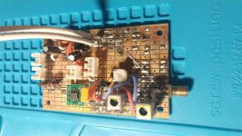
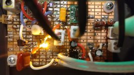
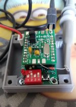
So here is the TA7642 detector. There seems to be almost a cult following on this chip, and in reading up on it, NE602/TA7642/LM386 receivers look to be quite common.
Because of the high gain of the TA7642 ( about 65-70 dB at 455 KHz ), it is being driven from the output of the first IF stage. The yellow LED is used here as a voltage regulator, applying 1.9 VDC to the chip. The blue LED, to the right of the first IF, is used to give a visual indication of the gain in the IF stages; the brightness of the LED being somewhat proportional to the gain of the stages. I have the IF gain turned way down to avoid overloading the TA7642.
The feedback resistors / voltage divider between pins 2 and 3 of the chip looks to be fairly critical, and as far as I can tell there is no formula to calculate it. The data sheet says the typical AGC range is 30 dB. I can't really tell - I am listening to WTWW 5085 KHz right now, and it sounds relatively constant except for deep fades. It's a lot better than the no AGC diode detector. The feedback resistors / voltage divider seem to affect the recovered audio more so than the AGC, as far as I can tell. I have fiddled with this a bit, and have it working pretty well but there is probably room for improvement. I probably don't have the level of interest needed to do much more trial and error with it.
It sure doesn't take up much space - if it works well enough, it would probably free up more than enough space to go back to a 45 MHz first IF, and a crystal oscillator controlled second mixer to 455 KHz. I wish I had found this chip a couple of weeks ago.
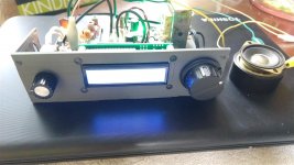
The other "chassis" warped in my car, again, so I printed another with a knock out for a small speaker.
BTW, here is some interesting stuff I somehow ran across researching this chip: N4TRB Amateur Radio
Because of the high gain of the TA7642 ( about 65-70 dB at 455 KHz ), it is being driven from the output of the first IF stage. The yellow LED is used here as a voltage regulator, applying 1.9 VDC to the chip. The blue LED, to the right of the first IF, is used to give a visual indication of the gain in the IF stages; the brightness of the LED being somewhat proportional to the gain of the stages. I have the IF gain turned way down to avoid overloading the TA7642.
The feedback resistors / voltage divider between pins 2 and 3 of the chip looks to be fairly critical, and as far as I can tell there is no formula to calculate it. The data sheet says the typical AGC range is 30 dB. I can't really tell - I am listening to WTWW 5085 KHz right now, and it sounds relatively constant except for deep fades. It's a lot better than the no AGC diode detector. The feedback resistors / voltage divider seem to affect the recovered audio more so than the AGC, as far as I can tell. I have fiddled with this a bit, and have it working pretty well but there is probably room for improvement. I probably don't have the level of interest needed to do much more trial and error with it.
It sure doesn't take up much space - if it works well enough, it would probably free up more than enough space to go back to a 45 MHz first IF, and a crystal oscillator controlled second mixer to 455 KHz. I wish I had found this chip a couple of weeks ago.
The other "chassis" warped in my car, again, so I printed another with a knock out for a small speaker.
BTW, here is some interesting stuff I somehow ran across researching this chip: N4TRB Amateur Radio
Attachments
I also have a RP, which is gathering dust.
Is there an easy way to run it as an SDR without having
to learn Hermes and the other prehistoric boards? It's
annoying to emulate a board no one would use any more,
there must be a shorter, direct way? SSB/CW is minimum,
WSJT would be appreciated.
I will be starting at zero knowledge with SDR, so I can't be of any help, yet.
But here are a couple of pages I bookmarked that are specific to SDR on the RP:
Red Pitaya SDR
Building an SDR around a Red Pitaya
There is a 16 bit RP now, optimized for SDR, but thanks to the virus, my businesses have gone to Hades, so I will not be upgrading for the foreseeable future.
Too soon to tell.... if it works well enough ...
On the one hand, it ( TA7642 ) has very good audio output, easily capable of driving any of the common audio power IC's without an intermediary stage. And the AGC seems to work at least as well as the usual transistor radio, where only one IF stage is AGC controlled.
On the other hand, on the AM BCB, there is a single strong station that blankets the whole band. Fortunately, this is the one I want to listen to. I can eliminate this by cranking the IF gain down to about nothing, or even a little negative. Undoubtedly my complete lack of front end selectivity aggravates this situation. But this does not occur on shortwave. I'm also not using it right - it has a really high input impedance, and I'm driving it from a low impedance. So more experiments are needed. I only have the one part, so I can't be aggressive with it until I can get some more.
It looks like this board is becoming more of an experiment board, and less of a functional board to put in actual service, although I am listening to it right now.
So I've played with the TA7642 for a bit now, and I'm still not sure what to think of it. I moved it up closer to the take off point for the volume control, and played some with a variable resistance in between the input and output pin to move the AGC point around. This worked, sort of, but having to do that seems to defeat the point of it being simple. I think the best configuration was having the primary of a 455 KHz IF xfmr in series with the AGC resistor between the input and output pins, and feeding the RF input signal into the center tap of the xfmr, but that was a week ago, and I don't have enough interest in it to change it back to that configuration.
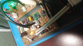
The good things about this chip are that it is cheap, the almost unbelievably simple hook up, the high gain, the low operating voltage, lots of audio output, and AGC that actually works pretty well if the input is right ( big if ).
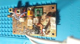
The bad things about this chip are are the almost unbelievably simple hook up, the high gain, and it needs a very low operating voltage. It overloads really easy. It would probably work better connected directly to the mixer output, but I still have it hooked to the first IF so I can have an additional tuned circuit before the chip. The murata filter seen on the board is tacked down, but is not in circuit - the only selectivity here is the two pole filter at the mixer and the IF transformer, plus the single tuned circuit at the front end ( SW only ). The IF amp is biased just enough to pass signal through it; anything more and the chip overloads.
The current build is adequate ( barely ) for my application of picking up a few local MW and SW stations, so further tinkering on it will not be pursued. I don't see the TA7642 as a substitute for a real IF and detector system except in the very simplest of applications. Which I guess is the intended use, so maybe my criticism is unfair. It might work better at higher IF's where it is less sensitive. I found the old piece of perf board from a few years back that has good high and low pass filters on it, and it looks like it would fit on the transceiver breadboard when it is moved to a permanent home ( or I could just print one for the RX ), so I'll probably try to build up a broadcast receiver on it.
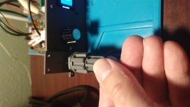
The last two pictures are parts ( made on the $100 box of parts printer ) to make concentric controls for individual pots or encoders with D flat shafts. These need to be trimmed and cleaned up a bit, but it looks like this has potential to save quite a bit of horizontal panel space, at the expense of only a few extra mm of vertical height.
The good things about this chip are that it is cheap, the almost unbelievably simple hook up, the high gain, the low operating voltage, lots of audio output, and AGC that actually works pretty well if the input is right ( big if ).
The bad things about this chip are are the almost unbelievably simple hook up, the high gain, and it needs a very low operating voltage. It overloads really easy. It would probably work better connected directly to the mixer output, but I still have it hooked to the first IF so I can have an additional tuned circuit before the chip. The murata filter seen on the board is tacked down, but is not in circuit - the only selectivity here is the two pole filter at the mixer and the IF transformer, plus the single tuned circuit at the front end ( SW only ). The IF amp is biased just enough to pass signal through it; anything more and the chip overloads.
The current build is adequate ( barely ) for my application of picking up a few local MW and SW stations, so further tinkering on it will not be pursued. I don't see the TA7642 as a substitute for a real IF and detector system except in the very simplest of applications. Which I guess is the intended use, so maybe my criticism is unfair. It might work better at higher IF's where it is less sensitive. I found the old piece of perf board from a few years back that has good high and low pass filters on it, and it looks like it would fit on the transceiver breadboard when it is moved to a permanent home ( or I could just print one for the RX ), so I'll probably try to build up a broadcast receiver on it.
The last two pictures are parts ( made on the $100 box of parts printer ) to make concentric controls for individual pots or encoders with D flat shafts. These need to be trimmed and cleaned up a bit, but it looks like this has potential to save quite a bit of horizontal panel space, at the expense of only a few extra mm of vertical height.
Attachments
Here are some files demonstrating the AGC action and strong audio output of the TA7642. These were recorded as .wav files on my phone held up to a small communications speaker, and then converted to .mp4. My phone does not do AGC; I wish it did, but it doesn't - the only audio leveling is the TA7642. The source is WTWW 5085 KHz shortwave, the antenna is 12 gauge speaker wire in the ceiling of my office for speakers I haven't got around to installing yet. Probably 6 or 7 meters length; single floor building.
_4 is the circuit in post #723; the notable thing here is the rancid 120 Hz AC hum - this is diode noise coming in on the antenna ( common with random wire antennae ).
_5 is the most recent circuit; 100 nF disc caps were placed across each diode in the bridge rectifiers to get rid of the hum / buzz.
The '7642 is not that bad, especially for something in a TO-92 case - I've heard worse.
Attachments
Last edited:
Me? I can barely program a coffee pot to turn on in the morning.
I knew Atari Basic, sort of, when I was in college.
I knew Atari Basic, sort of, when I was in college.
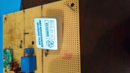
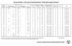
Do any of you guys have specs on this KVG filter? It is marked XF-107 S118. Obviously it is 10.7 MHz; I think it is AM bandwidth.
The closest data I can find is for an XF-107 S 18, that looks like an AM filter.
The closest data I can find is for an XF-107 S 18, that looks like an AM filter.
Attachments
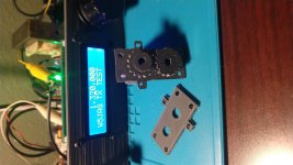
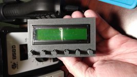
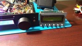
A template mount for the common 0-40 MHz DDS modules widely available from the usual suspects, that accommodates the on board pushbuttons.
The long reach required to get from the front of the LCD to the PCB mounted buttons makes the whole thing seem overly fragile to me. I suspect the first approach of using more robust switches is the better approach, but this template saves some space on the front panel.
The pushbuttons need some work.
Attachments
New line of Mini Circuits low pass filters that Mouser has begun carrying.
A bit pricy by my standards, but I was not getting anywhere making my own low pass filters with SMD inductors, so I thought I would give this a try.
They make them in several different cut off frequencies. This one is 30 MHz.
A bit pricy by my standards, but I was not getting anywhere making my own low pass filters with SMD inductors, so I thought I would give this a try.
They make them in several different cut off frequencies. This one is 30 MHz.
Attachments
So how are you fellas liking your nano vna's?
Looks like the same bunch have come out with a nano spectrum analyzer, good to 350 MHz. $50 USD from a stateside seller:
TINYSA TINYSA
The RP is meeting my needs for now, but for $50 ...
Looks like the same bunch have come out with a nano spectrum analyzer, good to 350 MHz. $50 USD from a stateside seller:
TINYSA TINYSA
The RP is meeting my needs for now, but for $50 ...
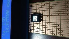
This is the QRP Labs Prog Rock, basically an Si5351 synthesizer on a minimalist controller, that can be programmed for twenty four ( 24 ) discrete frequencies up to about 300 MHz.
It looks a little rough - I assembled the Si5351 board first, then realized I was missing parts for the controller. Upon RTFM, I realized the Si5351 board should be assembled differently than when used on the VFO - I had to remove parts from the Si5351 board and then install them on the controller. So it took twice as long to build it as it should have
When I hooked up the RP to test it, I checked for a firmware update and there was one. For whatever reason, the over the air firmware update broke the RP. So, I had to find a program to repartition and format the SD card which was trashed, and then download an image file and the software to recreate the RP SD card.
Anyway, now that the RP is working again, it looks like the Prog Rock works. The VFO defaults to 10 MHz, and this device looks to be running at 10 MHz, so I assume this is normal. There is another manual for how to program this device, so I guess I will have to RTFM - I'm done with DIY for the day.
The pics are the clock 0 output. As expected, it's not pretty.
Attachments
This is the manufacturer of your filter:
Filter in metal package
But you should be able to get the S-parameters with your RP! 🙂
That unshielded proto board does no justice to the filter. If it is like the
9 MHz filters that I have, it suppresses below -100 dB.
Gerhard
Filter in metal package
But you should be able to get the S-parameters with your RP! 🙂
That unshielded proto board does no justice to the filter. If it is like the
9 MHz filters that I have, it suppresses below -100 dB.
Gerhard
Last edited:
Thank you, Gerhard.
I don't ( yet ) have the VNA bridge module for the RP, although it is on my to get list, and soon.
I'm not sure what I am going to do with this filter - I'm still annoyed that I didn't complete an up conversion rig, so this filter may wind up in a simple general coverage receiver that can control a simple transmitter. I've bought another QRP Labs Si5351 based VFO, another AD9850 DDS VFO, the Si5351 crystal replacement thing, a bunch of discrete crystals for conversion oscillators, that mini circuits low pass filter to test, not to mention all the mixer parts and boards and other left over stuff ( over fifty smd SA602, and hundreds of smd dg mosfets ), and I've been scheming various ways to do this. I'm still unwilling to concede defeat on double conversion.
I have at least one of the matching KVG 10.7 MHz sideband filters ( somewhere ), but I'm not sure that I have both sideband filters. I have some matching McCoy 10.350 MHz sideband filters, and some matching Collins 455 KHz mechanical filters, but I would have to dismantle the mainboard for the first SSB rig I made to get the Collins filters. I'm sure that I've moved past that "tech" and I'll never use it again, but I'm not really sure I want to start robbing parts from it either.
I do have some questions on how to try to do RF shielding on these prototype boards, and I'll be asking them at a later point. I remember those Laird boxes from earlier in this thread.
It's been about three years since I started soldering on this project and I'm still not even close to a finish point; I'm sure I've learned something, sometimes I'm not sure exactly what ...
Interesting! I look forward to hearing how it performs!
Getting closer to finding out.
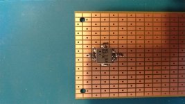
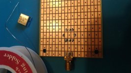
Plan A was to mount it pads down, as intended. Plan B was to invert it, tack the edges of the can down, and jumper from the pads on the filter to the pads on the board. It turned out that the pads on the filter lined up perfectly with the pads on the prototype board, so I started with Plan A.
I hadn't soldered an SMD part with these kind of pads before, so I didn't know how to do it. I have an air gun, but don't have any solder paste with me, which might be the best solution, so I started by putting some solder on the board where the pads would land, and then setting the part and trying to solder a pad to get it tacked down. That didn't work. So I added some flux to the filter pads, and tried it again. Still didn't work. So, I added solder to the filter pads, and that combination worked.
It ended up being easy to set the part, although it took a bit more than an hour to finish it with all the grounds. The schematic shows a DC path through the part, so I put 100 nF caps on both ends of it.
If I had the Si5351 test jig with me, it would be pretty easy to use it and the max hold function of the RP to get a fast sweep of the response. I only have the RP here, so checking the response will be more tedious with the generator built into it. I may or may not get to that later today.
Attachments
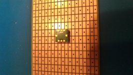
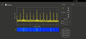
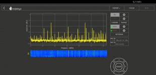
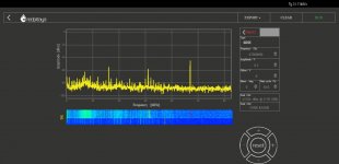
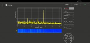
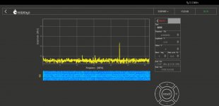
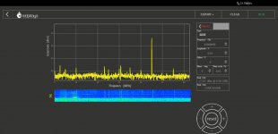
My test setup is not optimal - it's not matched at 50 ohms at the output ( unless the mixer counts as a 50 ohm load ), and my cabling is poor, but the RLP-30 looks to be soldered satisfactorily and meets its specifications. The RP can only generate 50 MHz or less, so I just picked a few points where the data sheet had a spec for comparison.
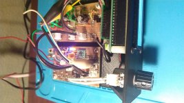
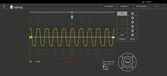
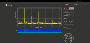
The mixer is a surplus Mini Circuits TUF-3. I chose this because I didn't experiment much with the ring diode mixers the first time around, and this one is supposed to have good response down to 150 KHz. The mixer looks to be working - the inputs are 14 and 31 MHz. I'll come back later and ( try to ) optimize the matching at the ports of everything.
The general idea here is a 150 KHz - 30 MHz broadcast receiver, double conversion ( low VHF first IF ), AM only, in its first iteration to get it working. Maybe that will be the end of it. Or when that is working, maybe add SSB/CW selectivity and detection, and then maybe add some other features, like control of an external transmitter of some sort. Probably a lengthy and fluid undertaking; I'm in no hurry, and there is still much left to be done on the single band transceiver. I'm figuring I won't need an RF amp for a broadcast receiver, or at least to get one up and working, so I just left an empty space there for now.
Mouser has a new line of Mini Circuits mixers - look to be the complements to the new low and high pass filters.
Attachments
-
 MCL TUF_3 14 MHz 31 MHz mix.jpg107.3 KB · Views: 104
 -
 MCL RLP_30 50 MHz out.jpg102.3 KB · Views: 89
 -
 MCL RLP_30 47 MHz out.jpg101.6 KB · Views: 93
 -
 MCL RLP_30 37 MHz out.jpg98.1 KB · Views: 89
 -
 MCL RLP_ 30 10 MHz input.jpg96.7 KB · Views: 110
 -
 IMG_20210124_091732348.jpg131.4 KB · Views: 108
 -
ADE-1+.pdf269.3 KB · Views: 82
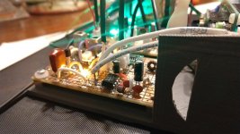
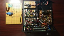
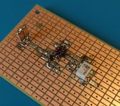
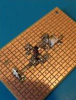
The first IF amplifier / second mixer board is mostly done. It looks like whatever it is going to be, it is going to get there by way of separate modules.
I did not have the correct parts with me to match the 45 MHz filter to 50 ohms, so it is not hooked up on either end. I may not have them back at home base; if I have to order them, I will likely pull this filter and substitute an SMD filter in its place. Mouser is now stocking some, although they are 30 KHz wide instead of 20.
The IF amp is the same circuit as the broadband amps in the transverter, with some component values changed to ( hopefully ) make it more suitable for low VHF use. The transistor is an MMBT5179, and is presently set for 20 ma at 12 VDC so it can be run a lot harder if need be. It has no provision for AGC. The coils in the transverter were FT37 toroids, but FT23 are used here.
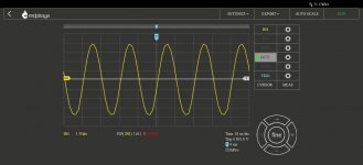
At 45 MHz, it shows about 25 dB gain. The RP does not have a clean enough sine wave at 45 MHz to look for clipping, but at 10 MHz, it starts to flatten at 0.45V input. The amp loses about 3 db from 2 to 30 MHz, and another 10 dB between 30 and 40 MHz, and then flattens out and stays flat to 50 MHz which is the upper limit of the RP generator, so all I can test for today, but I hope that gain reduction / flattening is the feedback starting to work. My test cabling is not very good; I don't have the right stuff with me.
I used a 0402 capacitor in the collector to base feedback loop; so not really looking forward to changing that part if it comes to that. The 0402 parts are exactly the dimension of the inter pad space, so there is zero margin for error in placing them on these large pad prototype boards. I have some 0603 parts and may start trying to use some of them.
The mixer is a Mini Circuits ADE-1+ 7 dBm part. The remaining space on the board will be for a crystal oscillator / buffer amplifier to drive the mixer. For now I will likely use that Prog Rock for the fixed LO injection, and then come back to, and build out, a crystal oscillator later. I already have the parts and rocks to go from 45 MHz to any of the common low frequency IF's.
I did not have the correct parts with me to match the 45 MHz filter to 50 ohms, so it is not hooked up on either end. I may not have them back at home base; if I have to order them, I will likely pull this filter and substitute an SMD filter in its place. Mouser is now stocking some, although they are 30 KHz wide instead of 20.
The IF amp is the same circuit as the broadband amps in the transverter, with some component values changed to ( hopefully ) make it more suitable for low VHF use. The transistor is an MMBT5179, and is presently set for 20 ma at 12 VDC so it can be run a lot harder if need be. It has no provision for AGC. The coils in the transverter were FT37 toroids, but FT23 are used here.
At 45 MHz, it shows about 25 dB gain. The RP does not have a clean enough sine wave at 45 MHz to look for clipping, but at 10 MHz, it starts to flatten at 0.45V input. The amp loses about 3 db from 2 to 30 MHz, and another 10 dB between 30 and 40 MHz, and then flattens out and stays flat to 50 MHz which is the upper limit of the RP generator, so all I can test for today, but I hope that gain reduction / flattening is the feedback starting to work. My test cabling is not very good; I don't have the right stuff with me.
I used a 0402 capacitor in the collector to base feedback loop; so not really looking forward to changing that part if it comes to that. The 0402 parts are exactly the dimension of the inter pad space, so there is zero margin for error in placing them on these large pad prototype boards. I have some 0603 parts and may start trying to use some of them.
The mixer is a Mini Circuits ADE-1+ 7 dBm part. The remaining space on the board will be for a crystal oscillator / buffer amplifier to drive the mixer. For now I will likely use that Prog Rock for the fixed LO injection, and then come back to, and build out, a crystal oscillator later. I already have the parts and rocks to go from 45 MHz to any of the common low frequency IF's.
Attachments
- Home
- Member Areas
- The Lounge
- No RF gear here?