smaller antenna up on the cliff and an amplifier
I had thought about a similar setup for TV reception but I have no access to the land up top to test with a spectrum analyzer.
Unfortunately the bunch that legally own the land at the top of the cliff seem to want nobody up there. They have no trespassing signs and seem to defend their ground. I have no personal experiences, but the neighbors unanimously tell me to stay away. Some say they are involved with drug people. I hear quad bikes and gunshots up there all the time and friends who used to live near there tell me about rotting animal carcasses and other undesirable stuff.
The cliff face itself is their property but a a wire attached to a tree up about halfway would not be noticed. The ground up there had become very unstable with the flooding and mudslides this winter. I will see what summer brings.
The FCC would probably freak out.
They can't freak over what they can't find. It would be a simple matter to grab a bunch of spectrum and shift it up into the microwave range where a flat panel antenna could beam it down the hill. RX could be powered by a small solar panel and a LIPO battery. TX would be a different story.
Retransmitting TV signals in an amateur radio band is illegal, but remote operation of an amateur radio station via an RF link in a ham band is OK.
I will likely hang some sort of wire antenna for HF. I still have the W5GI mystery antenna that I used in Florida. I also have a 30 MHz to 1.3 GHz cheap Ebay discone that I may put up on a mast along with a DIY amp and antenna system to get cell service.
Searching for signal with an "antenna on a stick" must wait for a month or two. I found a good spot last winter for TV (two local stations) and cell signals, but they vanished once the leaves returned to the trees.
http://www.diyaudio.com/forums/the-lounge/309531-rf-gear-23.html#post5410251
I would put a large flat vertically mounted metal surface or sphere up in the sky mounted atop of a pole and bounce your signals off of it to get out of the valley. It would need to be rotatable.
Last edited:
mounted atop of a pole
According to the Google earth topography map It would need to be a 400 foot pole to get out of the "holler"!
The GPS in my phone has us at 660 feet above sea level. A relative's house at the top of the ridge to our west is at 1340 feet using the same phone. That ridge slopes down to the Ohio river at 620 feet.
The top of the ridge to our east is around 1200 feet.
The trough we are in runs nearly north and south, but we are at its lowest point. The required launch angle for north and south bound signals is doable at HF. UHF and beyond is basically line of sight, so relatively useless here except for EME (moonbounce) which has limited visibility because of the ridges.
I was experimenting with bouncing signals off the ISS in Florida. Doppler shift is the big killer for that mode of operation as the limited time and distance window.
Hmm that is a rather unique situation you have there.
Have you already considered placing a repeater on a piece of land that your relative owns?
Aside from that you are stuck with using the internet (echolink & IRLP) and HF operations.
The only other option would be to use a local 10m band repeater. Unless you stick to using VHF/UHF while running mobile.
Using HF isn't all that bad. Neither is satellite television, there is nothing but garbage on tv anyway, we here are using netflix/roku box.
Last edited:
Hi George,
Can you "see" the DSS satellites? That is one way to get TV and tunes. Not perfect, but your angle should be a lot better than we have up here (~35° I think it was). TV is a lot better than cable, which it sounds like you can't get. Right now we are on fast DSL for TV and internet. Close to 100 Meg / sec last time I checked. We use Netflicks a lot, and normal broadcast delivered on DSL. We were on the Bell satellite system before that and it was very good. Before that we were evil DSS pirates and the quality was darned good on that. Pirates you say? Yes, we weren't allowed to pay for DSS and so were forced to use hacked entry into the system.
-Chris
TV is a lot better than cable, which it sounds like you can't get.
We have cable. My wife can't exist without TV, so we get 400+ channels and there still isn't anything worth watching. I can go for days without turning the TV on, but the internet is a different matter. This PC launches diyAudio automatically on the second screen whenever it's on. The Comcast cable goes on for a couple more miles past us. Being out in the sticks you would expect slow internet, but I get good speed. I just measured a 10 mS ping, 298 Mbps down and 12 Mbps up. I have seen 350+ download speed early on Sunday mornings. It can also slow down to the mid 100's about 6PM on weekdays. I have no problems streaming two channels of 4K video simultaneously even in the afternoons.
A lot of people here have DSS dishes. There are also companies running wireless internet in the 902 -928 MHZ ISM band. Their service isn't cheap.
Have you already considered placing a repeater on a piece of land that your relative owns?
I have thought of several ways to make things work, all will need some experiments and testing to see what works.....all in good time. Too many projects right now.
Does your wife know my wife? She's the same, and I can do without the TV. It's okay for some things, and the news. Like you, the internet is far more important than anything else.
Projects. Yup, know what you mean. Retirement only means I can do more stuff. 🙂
-Chris
Projects. Yup, know what you mean. Retirement only means I can do more stuff. 🙂
-Chris
..... Make the switch to SMD! ......
I ordered a cheap hot air rework station / fine tip soldering station and a few other bits just to get started.
I have a huge inventory of through hole parts, so this will be a gradual transition. Some SMD parts on breakout boards to connect to through hole wiring on perfboard, is the plan for now.
Since learning the hard way that the Si5351 synthesizer runs +13 dbm, I thought I might get some SMD +13 dbm mixers. That would free up a lot of room on that double balanced mixer board. Maybe I need to scrap that board and start a new one. I'm sure there are a lot of SMD only mixer IC's that I've never even considered.
I thought that this project would be just hooking that synthesizer up, stringing a few obsolete linear IC's together, and it would be done in a month. Almost a year into it, and I'm not even past the mixer(s) 😱. I figured that would be the fast / easy part.
Win W5JAG
....
Last weekend I built a Colpitts oscillator, published by some $DEITY.
It turned out that the published circuit and the simulations / measurements
had not much in common. :-(
(It can oscillate on every overtone, but not on the intended one. Trap was deleted.) ....
Is this the oscillator for the Red Pitaya SDR? Are you going to double it twice for UHF, or use an overtone?
Win W5JAG
No, I must admit that this was kind of a revenge ;-)
I proposed a Driscoll osc some weeks ago and $DEITY
called that amateurish, unless it was a Colpitts specially
superoptimized by a special CAD program by HIS posse.
He also touted an article of his in Microwave Journal that
demonstrated the close correlation of the CAD and the
real measurements.
R. Feynman wrote in his cargo cult lecture how important
it is to repeat previous experiments to make sure that you
get the same results and that you don't fall victim to
systematic errors. So I built the Colpitts from his circuit
diagram to compare a Driscoll with the _same_ crystal to
it. But with a dozen of different overtone crystals there was
not one that would oscillate on the correct overtone.
The required trap for the wrong harmonics was missing, and that
suggests that both the published simulations and measurements
do not have a lot in common with the published trap-less circuit.
That hurts somehow, since he did have some influence
on me when I was choosing my profession. 😡
With the Red Pitaya, I have this project of motorcycle-based
EME. But I doubt that I'll be ready in summer when I go to
Scotland / Isle of Skye. That does not mean EME-motorcycle-mobile,
only that everything required can be transported by bike.
A friend of mine has build a huge antenna array for 432, a 6 element
and 10 Watts should be enough for a 2 way CW EME contact.
I think that I could generate 50 Watts from Li ion batteries
and a 10 element should be small enough to be transported by the
R1200GS. Weight is no problem, but room is. Required transmitting
time would hopefully be short, so 2650 Li-Ion batteries would work.
I choose a Crystek CVHD-950 100 MHz oscillator, that has quite
good phase noise, I wonder how they make it in that small package.
It is a VCXO, so I can lock it to an external 5/10 MHz reference in case
it is necessary. I double it twice to 400 MHz, the Pitaya gets the 32 MHz
difference. It helps tremendously that I can use every IF frequency up to
60 MHz. There are nice 400 MHz SAW filters from EPCOS/ TDK, and also
for 432 MHz from Johanson. No trouble with tuning, and all is available from
DigiKey & Mouser, cheaply.
Now it's bed time here,
cheers, Gerhard
I may be the last person on the planet who wanted to build a simple analog FM stereo tuner. In the unlikely event I am not, there are some simple FM front ends for sale on eBay right now. These once common parts have become virtually unobtainium:
FM Radio Module, Toko TMC103A, varactor, transformer | eBay
SAMSUNG FM compact radio tuner KCF201BVA | eBay
I got one of the Toko's, and two of the "Samsung", received all of them, and squirreled them away in the parts stash.
The Samsung is the vertical mount version, I used a horizontal mount part, because it was all I had at the time. I have attached the data sheet for the Samsung, as well as the KSE tuner that I used. These look to be equivalent parts, except for mounting orientation. I can't find data on the Toko part.
Win W5JAG
Attachments
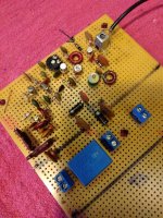
I added a low pass filter ( 90 MHz - 3 dB ) to the tunable LO, and a single tuned circuit to the fixed second LO to try to cut down on the junk going into the unbalanced mixers. The single tuned circuit is very sharp - it can completely eliminate the second LO when off tune. The coil is wound for about 1.3uH, and with the capacitor, it can tune the second LO at either injection frequency - 54 Mhz or 36 MHz to select sidebands.
The second mixer just isn't right - after the picture was taken, I added a pot in the source to play with the current, and may fool with the bias on the gates; but it is way too noisy. It's better when the output is chased with a filter, but I just don't think it's right. I don't seem to be getting anywhere with it, and I can't seem to fix it. As a last resort, I guess I could replace the FET in the event it's been damaged - in addition to the lightning jolt, it's been soldered and unsoldered a lot, but I think the likely outcome is that it will be replaced with something with at least some balance.
With the FT-950 fried, I'm using an FT-817 as the "IF". This is not a great receiver, but I don't think it is the problem. It's a bit of handicap not having anything suitable to look at the mixer input and output.
At least my soldering is a bit better - the FM tuner board soldering, back around post 86, is really rough looking - no way to sugar coat it, it's just downright bad - and it caused me some real difficulty. It seems like there is just not enough flux in this new solder I've been using - I'm now adding flux to the joints before soldering, and it seems to have made a big difference.
Win W5JAG
Attachments

The first mixer is a genuine RCA 40673. The IF amp and second mixer are marked Siliconix 40673.
Killing some time tonight, I tried grounding the case of the second mixer, and observed a pretty dramatic noise reduction. I also observed that this completely removed any effect from the variable resistance I placed in the source. I observed a similar effect with the other Siliconix. The RCA does not exhibit this effect.
I suppose it's possible one or both are oscillating, but I probed them with a wavemeter and didn't find anything. I had some concern putting a tuned circuit in the gate would make an oscillator, but the RCA responded real well to this when I built the first mixer on a piece of scrap board. The Siliconix doesn't seem to.
I'm not sure what to conclude from this. I'm wondering if one or both of the Siliconix are junk. Or maybe they're not really 40673's. I bought them probably thirty years ago, before counterfeit junk was a concern. A real 40673 should have no problem with 45 Mhz, and apparently doesn't care what you do with the case. I have some "better" TI and Motorola MOSFET's. Maybe I need to try them. I don't have any more RCA parts, and they are probably unobtainium now. Genuine ones, anyway.
Win W5JAG
Hi,
first time I hear that Siliconix made 40673, but then I have some
LT1028 made by Maxim. Got them from their local distributor in .de
so they are probably OK. At least they work normally.
I still have some 40673 from RCA, and also 3N140/141 (the prime version)
and 40841. It was common to have a ferrite bead on the gate2 wire
and decoupling it then to GND.
They often were used here in 144 MHz transverters, both for receiving
and transmitting. That worked nicely. I had some QSOs with a 40673
in the 2m "PA" 🙂 5 mW or so.
They are easy to use for AGC, but when the gain drops, so does
the IP3.
I think there are later DGFETs from TI, Infineon and NXP.
Type numbers BF998 .. BF1000 (?)
They don't seem to have a lot of market penetration, maybe
for TV tuners.
Take a look at the bottom board in post #216. That is excellent
for RF work. You get a relatively ideal ground plane and attaching
components to GND takes just a solder blob on the top side.
The bottom layer is just square pads. There is also a deluxe
version with plated-through holes. That makes the pads stick better
to the board, but the cheap version is usually good enough.
Gerhard
Last edited:
btw, I picked up Eric Nichol's recent book "Receiving Antennas" from the ARRL. He does a good job of explaining why a separate receiving antenna may be a good investment.
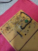
The 100K resistor, from gate 2 to gnd, marked here with the arrow, should not be there.
Hard to tell from my lousy cell phone pics, but on the underside of the board, there is already a 100K 1/8 watt resistor from the source to gate 2 to bias that gate.
I don't know if this is the root of the problem, but it would be cutting the dc bias on that gate in half. May be a few days before I can check it out.
Win W5JAG
Attachments
That 100K resistor was it.
It's comfortably receiving a Cardinals ballgame on a fifty (50 !) watt (night time) BCB station, 1.58 MHz --> 45 MHz --> 9 MHz, 20 foot piece of wire connected to the junction of the high pass and low filters, RF amp off, -20dB attenuator engaged on the FT-817. It's showing S6, modulation peaking to S8.
I'll probably tinker with the bias and source resistance to optimize it, then possibly dismantle it to play with some other ( balanced ) active mixer circuits.
Okay, I'll run them at full gain, and won't fool with AGC'ing them.
The SMD station was delivered this afternoon. I can move on to making big mistakes with smaller parts.
Win W5JAG
It's comfortably receiving a Cardinals ballgame on a fifty (50 !) watt (night time) BCB station, 1.58 MHz --> 45 MHz --> 9 MHz, 20 foot piece of wire connected to the junction of the high pass and low filters, RF amp off, -20dB attenuator engaged on the FT-817. It's showing S6, modulation peaking to S8.
I'll probably tinker with the bias and source resistance to optimize it, then possibly dismantle it to play with some other ( balanced ) active mixer circuits.
... They are easy to use for AGC, but when the gain drops, so does
the IP3. ...
Okay, I'll run them at full gain, and won't fool with AGC'ing them.
The SMD station was delivered this afternoon. I can move on to making big mistakes with smaller parts.
Win W5JAG
Take a look at the bottom board in post #216. That is excellent
for RF work. You get a relatively ideal ground plane and attaching
components to GND takes just a solder blob on the top side.
Gerhard -- what material is the "box" which you "solder blob" to the ground ring. Did you just tin-plate some copper board material?
Jack
So I'm following this thread (there are new-to-USA LF/VLF ham bands I'm interested in: New Bands! FCC Issues Amateur Radio Service Rules for 630 Meters and 2,200 Meters, I want to attempt to transmit as well as receive), and I google part numbers.
RCA 40673 comes up as a dual-gate MOSFET, a device I vaguely recall seeing in RF circuits over the decades. "The Art of Electronics" 2nd Ed. has a good intro to FETs, but barely mentions these dual-gate things. One of the Google hits is this:
The Curse Of The 40673: Zombie Components That Refuse To Die | Hackaday
<ducking and running>
Gerhard -- what material is the "box" which you "solder blob" to the ground ring. Did you just tin-plate some copper board material?
Jack
That is Laird Technologies BMI-S-205-F for the walls
< BMI-S-205-F Laird Technologies EMI | RF/IF und RFID | DigiKey >
The cover is BMI-S-205-S
< BMI-S-205-C Laird Technologies EMI | RF/IF und RFID | DigiKey >
This is 1.0 * 1.5", there are other sizes, too.
I think it is tinned iron, it sticks to a magnet and solders really good.
- Home
- Member Areas
- The Lounge
- No RF gear here?