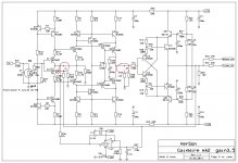
Here is updated GainWire mk2 with higher OPS bias suitable to better drive low impedance headphones. OPS bias is up from 30 ma to 60 mA and BD139/bd140 have now small heat sinks. As it needs more current now, the shunt regulars part is changed a bit, first the DN2540 source resistors are changed from 10R to 5R, maybe it will need a bit higher heat sinks for it.
There is one improvement in the shunt regulators. CCSs (J2 and J3) are now set to 10 mA about. That requires different jfets now 2N5486 or BF245B. They should be chosen for Idss of 10 mA or a bit higher. If the Idss is 10 mA then R2 and R9 are simple jumpers, if Idss is higher chose appropriate source resistors to get 10 mA. With that increased CCS current the shunt regulator output impedance is more constant up to 50 kHz.
Have a fun, Damir
Attachments

Thank you dadod
Should I consider a different output resistance when driving 16ohm phones ?
What if I use 600ohm phones ?
PS:
The boards are here 🙂
Should I consider a different output resistance when driving 16ohm phones ?
What if I use 600ohm phones ?
PS:
The boards are here 🙂
Thank you dadod
Should I consider a different output resistance when driving 16ohm phones ?
What if I use 600ohm phones ?
PS:
The boards are here 🙂
You can drive low and high ohm phones with no problem, no need to change output resistor.
Boards arrived. I need this only as a preamp for now. Can I use values in the latest BOM for this purpose or maybe 60mA for the output transistors is a little bit to much?
Boards arrived. I need this only as a preamp for now. Can I use values in the latest BOM for this purpose or maybe 60mA for the output transistors is a little bit to much?
You can use this last one or if you like better the previous one, attached.
Attachments
Got the pcb in perfect condition. Thank you.
Any disadvantage to use high idss ( 24 mA) jfets ( j309) with high value 1k degeneration resistors to reach 10mA curent source level in PSU??
Any disadvantage to use high idss ( 24 mA) jfets ( j309) with high value 1k degeneration resistors to reach 10mA curent source level in PSU??
Got the pcb in perfect condition. Thank you.
Any disadvantage to use high idss ( 24 mA) jfets ( j309) with high value 1k degeneration resistors to reach 10mA curent source level in PSU??
Yes it could be a problem, with 10 mA you will get a voltage drop of 10 V. Try to find nfet with lower Idss.
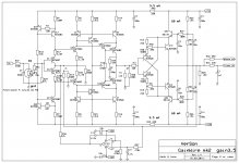
For those who like more choice here are more shunt mosfet combinations in shunt regulator part:
IRF510/IRF9510 or IRF530/IRF9530.
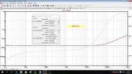
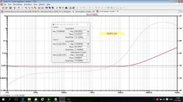
Bellow the output impedance plots for IRF510 and IRF530.
IRF510/IRF9510 or IRF530/IRF9530.
Bellow the output impedance plots for IRF510 and IRF530.
Attachments
Damir
May I ask what kind of level of heatsink temperature you find as acceptable without infuence on the circut performance ??
For PSU SK104 - 50mm seems mandatory to stay on the safe side if the amp would work in room temp + 30 C deg.??
( what I'm worry about is that Q2 Jfet is quite near the SK104 heatsink and after heatsink worm up the Id will go down strongly )
For BD139/140 I haven't found the type of the heatsink specyfied by You,
but best I could find Fisher SK522 - 50mm will show 35 K/W.
so in hot summer days we can reach easly near 70 C deg. on the heatsink
Is it still ok considering Q15-Q13 and Q14-Q16 placement?
I would prefer to have a preamp , which will work without surprises
Attachments
Well seems I did found answer for my own doubts 😎
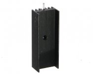
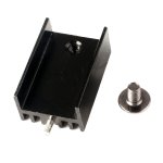
heatsink DY-CN-40 ( picture attached) is 15K/W 🙂 so it will keep the BD139/140 temperature always bellow 50 C deg.
This one is good, but shorter one is OK too.
Q2 is not jfet and doesn't need to touch the nearby heat sink.
Attachments
I presumed schematic has the precedence so here is what I noticed:
1. there are two R50 on PCB. One near the input should be R51 (1k)
2. there are also two R19 on PCB. Close to jumper J1(CFA) is correct one and R19 near the J2(NGNFB) should be R11.
Best regards, Milan
1. there are two R50 on PCB. One near the input should be R51 (1k)
2. there are also two R19 on PCB. Close to jumper J1(CFA) is correct one and R19 near the J2(NGNFB) should be R11.
Best regards, Milan
I presumed schematic has the precedence so here is what I noticed:
1. there are two R50 on PCB. One near the input should be R51 (1k)
2. there are also two R19 on PCB. Close to jumper J1(CFA) is correct one and R19 near the J2(NGNFB) should be R11.
Best regards, Milan
Yes, Thank you Milan. The layout (the PCB) was made before and I corrected schematic, but for the PCB it was to late.
In post http://www.diyaudio.com/forums/solid-state/235695-no-nfb-line-amp-gainwire-mk2-49.html#post4629715 in BOM, R40 and R41 are 33R but in the schematic are 2R2?
In post http://www.diyaudio.com/forums/solid-state/235695-no-nfb-line-amp-gainwire-mk2-49.html#post4629715 in BOM, R40 and R41 are 33R but in the schematic are 2R2?
Thank you again, the schematic is correct.
2R2 ; 4R7 ; 6R8
I hate those small value resistors
Hard to find them in good quality ( RN55 Dale starts from 10R ) with low ppm
I hate those small value resistors
Hard to find them in good quality ( RN55 Dale starts from 10R ) with low ppm
2R2 ; 4R7 ; 6R8
I hate those small value resistors
Hard to find them in good quality ( RN55 Dale starts from 10R ) with low ppm
Those positions are not so critical. I am buying all my resistors here in Poland, and now thy have discounts.
Transfer Multisort Elektronik - On-line katalog | 160 000 proizvoda u ponudi.
RN55 below 10R are in available mouser.com, but they are more expensive than the higher values. If you have more room on the PCB then go for RN60. Slightly more expensive but in my opinion it is worth it. Unfortunately only 4.7R is available in mouser at the moment.
I also found Ohmite WN series excellent. There are plenty of small values and they are 10-20ppm, but are expensive.
I also found Ohmite WN series excellent. There are plenty of small values and they are 10-20ppm, but are expensive.
- Status
- Not open for further replies.
- Home
- Amplifiers
- Solid State
- No NFB line amp (GainWire mk2)