I have decided to use 1 Meg and 1uF on my build (Cause I had these values already). Don't see a problem doing this. Corner frequency is almost the same.
Hopefully, I'll be finished building this weekend. 🙂 Then will post listening thoughts.
Hopefully, I'll be finished building this weekend. 🙂 Then will post listening thoughts.
This is what I normally use for the power amps... well, I will put 2 x 1uF caps (just got them in my stock). No big deal 🙂
The caps and the resistors do not add up to a lower roll off frequency.
The input cap and resistor set the Input Filter to a frequency.
The feedback cap and resistor set the integrator frequency.
If the same component values are used the two frequencies are the same.
One can add on a OUTPUT filter to reduce what rubbish is finally injected into the amplifier Input.
The input cap and resistor set the Input Filter to a frequency.
The feedback cap and resistor set the integrator frequency.
If the same component values are used the two frequencies are the same.
One can add on a OUTPUT filter to reduce what rubbish is finally injected into the amplifier Input.
The caps and the resistors do not add up to a lower roll off frequency.
The input cap and resistor set the Input Filter to a frequency.
The feedback cap and resistor set the integrator frequency.
If the same component values are used the two frequencies are the same.
One can add on a OUTPUT filter to reduce what rubbish is finally injected into the amplifier Input.
Good points!
In the GainWire I use the same type DC servo and increase in distortion at 16 Hz is quite big if instead of 2.2 uF I use 0.47 uF, probably because the distortion level is quite lower then in similar power amp, from 6.3 ppm to 17.5 ppm in NGFB mode and from .05 ppm to 1.15 ppm in CFA mode.
Did your distortion experiments look at the abilities of both the inverting and non-inverting DC servos?Good points!
Did any of your DC servos use a filter before injecting all the rubbish back into the input?
The caps and the resistors do not add up to a lower roll off frequency.
The input cap and resistor set the Input Filter to a frequency.
The feedback cap and resistor set the integrator frequency.
If the same component values are used the two frequencies are the same.
One can add on a OUTPUT filter to reduce what rubbish is finally injected into the amplifier Input.
Actually you're right, sorry - my mistake.
Did your distortion experiments look at the abilities of both the inverting and non-inverting DC servos?
Did any of your DC servos use a filter before injecting all the rubbish back into the input?
If you connect the DC servo output to the inverting amp input(where the GNFG is connected ) you need non inverting DC servo, and if is connected to the non inverting amp input then you need inverting DC servo (I did some simulation with inverting DC servo in my thread). I think that DC servo output filter is not needed, there are not rubbish at the output with properly design servo.
In fact, my non-inverting integrator design is based on my wrong assumption (I always used inverting ones before) and the more I think about it, the more doubts I have about its stability. OK, I will use 1uF and 1M and let's see how it will work. In bad case I will just invert the signal from the inverting integrator, already present at the power section.
Cool
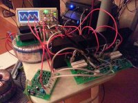
OK, here we go.
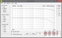
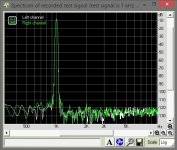
Excellent performance. Comparing to the setup with my OTA-based input buffer, this one gives slightly lower THD and slightly better phase shift at high frequencies (-3.7 deg against -5.2 deg @ 20kHz).
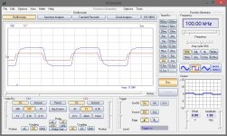
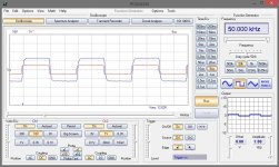
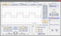
See the spectrum, Bode plot, square waves handling at 5, 20, 50 and 100 kHz.
I like such spectrums 🙂 Seems to be a little bit over-compensated (I did not change compensation values from my previous setup). I will play with it a bit - just had not enough time yet.
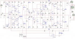
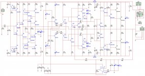
I slightly changed DC servo schematic - this one seems more robust to me, however I will research non-inverting servos deeper later on.
I tried the "normal" way of connecting the buffer and NFB (schematic 1), and then connected it the same way, as in my previous setup (schematic 2), when NFB is coming to the buffer output (in this case I have to connect the buffer to the other input of differential pair and use inverting servo of the power section).
No difference. Performance, all measurements are literally the same except 0.38db overall gain difference.
Output DC offset is less that 0.1mV (most of the time showing 00.0mV).
Sound-wise it is outstanding. Again - extremely natural sound of acoustic instruments, clarity at high frequencies, drums sound like they are in the room.
Dead quiet without the signal. I can touch the speaker grill with my ear - it is not possible to say if it is on or off. As one of my friends said - "It's not even silence. It's nothing".
Would be interesting to measure the output resistance - will do that later.
As well as the slew rate - it is clear it's high, but we'll see how high.
I consider this setup very successful.
If you have questions, ideas - let me know. It is up and running, I can test, measure, experiment, etc.
Damir, thanks for the great line amp design. It really rocks )
OK, here we go.
Excellent performance. Comparing to the setup with my OTA-based input buffer, this one gives slightly lower THD and slightly better phase shift at high frequencies (-3.7 deg against -5.2 deg @ 20kHz).
See the spectrum, Bode plot, square waves handling at 5, 20, 50 and 100 kHz.
I like such spectrums 🙂 Seems to be a little bit over-compensated (I did not change compensation values from my previous setup). I will play with it a bit - just had not enough time yet.
I slightly changed DC servo schematic - this one seems more robust to me, however I will research non-inverting servos deeper later on.
I tried the "normal" way of connecting the buffer and NFB (schematic 1), and then connected it the same way, as in my previous setup (schematic 2), when NFB is coming to the buffer output (in this case I have to connect the buffer to the other input of differential pair and use inverting servo of the power section).
No difference. Performance, all measurements are literally the same except 0.38db overall gain difference.
Output DC offset is less that 0.1mV (most of the time showing 00.0mV).
Sound-wise it is outstanding. Again - extremely natural sound of acoustic instruments, clarity at high frequencies, drums sound like they are in the room.
Dead quiet without the signal. I can touch the speaker grill with my ear - it is not possible to say if it is on or off. As one of my friends said - "It's not even silence. It's nothing".
Would be interesting to measure the output resistance - will do that later.
As well as the slew rate - it is clear it's high, but we'll see how high.
I consider this setup very successful.
If you have questions, ideas - let me know. It is up and running, I can test, measure, experiment, etc.
Damir, thanks for the great line amp design. It really rocks )
Attachments
-
 01.jpg252.1 KB · Views: 801
 -
 Sch-option-02.jpg311.2 KB · Views: 412
 -
 Sch-option-01.jpg317.4 KB · Views: 388
 -
 GW-square-100kHz.jpg200.8 KB · Views: 214
 -
 GW-square-050kHz.jpg201.9 KB · Views: 207
 -
 GW-square-020kHz.jpg199.8 KB · Views: 233
 -
 GW-square-005kHz.jpg200.7 KB · Views: 610
 -
 Bode-02.jpg94.9 KB · Views: 629
 -
 GW-spectrum-1kHz.jpg76.8 KB · Views: 658
 -
 02.jpg257.5 KB · Views: 696
OK, here we go.
Excellent performance. Comparing to the setup with my OTA-based input buffer, this one gives slightly lower THD and slightly better phase shift at high frequencies (-3.7 deg against -5.2 deg @ 20kHz).
See the spectrum, Bode plot, square waves handling at 5, 20, 50 and 100 kHz.
I like such spectrums 🙂 Seems to be a little bit over-compensated (I did not change compensation values from my previous setup). I will play with it a bit - just had not enough time yet.
I slightly changed DC servo schematic - this one seems more robust to me, however I will research non-inverting servos deeper later on.
I tried the "normal" way of connecting the buffer and NFB (schematic 1), and then connected it the same way, as in my previous setup (schematic 2), when NFB is coming to the buffer output (in this case I have to connect the buffer to the other input of differential pair and use inverting servo of the power section).
No difference. Performance, all measurements are literally the same except 0.38db overall gain difference.
Output DC offset is less that 0.1mV (most of the time showing 00.0mV).
Sound-wise it is outstanding. Again - extremely natural sound of acoustic instruments, clarity at high frequencies, drums sound like they are in the room.
Dead quiet without the signal. I can touch the speaker grill with my ear - it is not possible to say if it is on or off. As one of my friends said - "It's not even silence. It's nothing".
Would be interesting to measure the output resistance - will do that later.
As well as the slew rate - it is clear it's high, but we'll see how high.
I consider this setup very successful.
If you have questions, ideas - let me know. It is up and running, I can test, measure, experiment, etc.
Damir, thanks for the great line amp design. It really rocks )
Valery, my good you are fast. If I could do my amps so fast, but I am very slow.
I am glad that you like it, and hope you will do some more listening sessions and present them here. I am impressed with your ability in electronic and PCB layout. Where have you got your PCBs produced?
Tell me why did you connect a diodes on the IPS output, protection of an overload?
best regards
Damir
Hi Damir,
I develop PCBs myself, mostly using DipTrace, and then there is a very professional PCB workshop in a neighbor city. I send my files (P-CAD) format to them and they produce top quality PCBs in 2-3 days, delivering them to my office with a courier. It's not cheap with small quantities (these last 2 costed $87 for both), but it is fast, reliable and high quality. Our hobby is a good way to spend some money anyway )))
The diodes. At one of my previous experiments with this power section, I had a strong line amp output signal fluctuation, resulting in Q18'th death (shorted) and then R6 and R17 lighting like bulbs. That was with +/- 52v rails. After that I added Q33, Q34 to keep Vbe of Q17, Q18 at a decent level and added those 2 diodes, just in case.
In normal operation this point is mostly current-controlled, voltages are very low there and those diodes don't influence the signal.
I will do some extensive listening and share the results for sure.
This design is a good candidate for building a stereo amp in a good enclosure. Like it a lot.
BR,
Valery
It's the rubbish that is being injected that leads to the extra distortion you have measured.................... I think that DC servo output filter is not needed, there are not rubbish at the output with properly design servo.
Now back to your unpublished distortion results.
What did you test and what were the results?
Andrew, I just looked at the integrator output with oscilloscope, sending different type of signals through the amplifier. There is a constant normal HF noise, very low-level. No sign of the signals going through the amp. Well, it may make sense splitting the resistor at the output and ground the middle point with some 1nF cap. Just to make it "perfect". But practically... works fine as is. I mean, this is not a major source of THD in the circuit.
Last edited:
The non-inverting with the input filter gives the opamp less work to do and stresses the opamp less.
That way the integrator is working with slowly changing signal levels and has not been troubled by having to process transients.
The opamp output will contain the error correction signal, which should be pure DC and some noise and some distortion of the signal it was handling.
One can reduce the effects of the noise and distortion by using the injection resistor as a part of an RC filter.
Using an inverting topology loses many of the benefits listed above. Omitting the output filter is simply short sighted.
Have you looked at using Gootee's simulations for DC servos?
It's the rubbish that is being injected that leads to the extra distortion you have measured.
Now back to your unpublished distortion results.
What did you test and what were the results?
No it's not rubbish, just not low enough LF roll off and it's solved with bigger value caps in the DC servo. If you want to include additional low pass filter at the servo output it should be of very LF and that means high value resistors or cap. In my opinion it's not needed. Cordell is talking of high frequencies program material or interference sneaking through the integrator and depends of the layout and that is not easy to simulate, in my simulation that was not reason for higher distortion as it was simulated.
I don't have(yet) the test gear to measure distortion. I have a signal generator and oscilloscope.
ps. Valery, maybe you can measure LF distortion with and without DC servo output filter??
Last edited:
Have you looked at using Gootee's simulations for DC servos?
Nope. But would be interested to look at them.
If you've got some link to help finding them - will be very much appreciated.
If the error correction signal is not pure DC, then it contains rubbish.
Rubbish = stuff not required as an error correction signal.
That rubbish will consist of noise and distortion and probably some interference.
Reduce the rubbish to ZERO and the DC servo cannot increase the amplifier distortion.
It is not simply a case of increasing the time constant of the inverting integrator.
Make it too slow/big and the servo will not correct the error. The correction will always lag the effect one is trying to reduce. Go too far and it may end up hunting (LF oscillation).
In Gootee's Thread I asked for information on servo system design. None came.
insert Gootee and servo and I'm sure the thread will come up.Nope. But would be interested to look at them.
If you've got some link to help finding them - will be very much appreciated.
ps. Valery, maybe you can measure LF distortion with and without DC servo output filter??
Will do
On the road till next Saturday
Hi All,
Greetings from Lithuania. I travel around Europe till the next Saturday, so testing will be on hold till I'm back to Moscow, though I will run some useful simulations 😉
For those who are interested, attached is a final schematic of Damir's line amp section, as I use it in my power amp, as well as corresponding PCB layout (in PDF).
I can share pcb in P-CAD ASCII, Gerber - just let me know what format is good for you.
Cheers,
Valery
Attachments
- Status
- Not open for further replies.
- Home
- Amplifiers
- Solid State
- No NFB line amp (GainWire mk2)