High performer
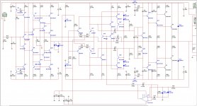
Damir, just ran some simulation tests - initial version of your line amp combined with my slightly updated TIS and untouched OP.
This one has got a bit higher rails, Richard - specially for you, ~250W @ 8 Ohm option 😉
Highly linear design with all CFA advantages - potentially appears a rather high performer.
Will test it live soon - already building the line amp, all the rest will be used from the current prototype with appropriate modifications with +/- 52V rails and separate regulated PSU for the line amp (also from the current prototype).
Attachments

Damir, just ran some simulation tests - initial version of your line amp combined with my slightly updated TIS and untouched OP.
This one has got a bit higher rails, Richard - specially for you, ~250W @ 8 Ohm option 😉
Highly linear design with all CFA advantages - potentially appears a rather high performer.
Will test it live soon - already building the line amp, all the rest will be used from the current prototype with appropriate modifications with +/- 52V rails and separate regulated PSU for the line amp (also from the current prototype).
Valery, I have to simulate your amp in LTspice, looks very interesting.
I see that you use a diamond buffer at the input, I prefer a Baxandal super pair instead. Maybe you can tray that way too. I suppose that you need more then two output pairs for 250 W?
Waiting your real life result.
Damir
Ah! Forgot to mention... in real life I use Sanken transistors (2SC2922/2SA1216 pairs) - they drive 250W with no problem, tested (though heat-sinks must be good as well as PSU).
I don't have models for Sanken stuff, however measurements on the prototypes show the results are very close to those Toshiba transistors, so I use them for simulation.
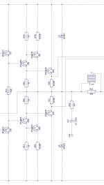
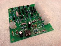
Attached is what the OP looks like in reality. Drivers are also from Sanken.
I don't have models for Sanken stuff, however measurements on the prototypes show the results are very close to those Toshiba transistors, so I use them for simulation.
Attached is what the OP looks like in reality. Drivers are also from Sanken.
Attachments
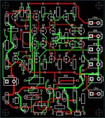
PCB
Slightly redesigned the PCB - left only the required part of the line amp, also had to place an integrator at the bottom - the one I have at TIS prototype is inverting, but for this design I need a non-inverting one.
Already ordered, expecting from the factory on Wednesday or so...
Slightly redesigned the PCB - left only the required part of the line amp, also had to place an integrator at the bottom - the one I have at TIS prototype is inverting, but for this design I need a non-inverting one.
Already ordered, expecting from the factory on Wednesday or so...
Attachments
Back to Zeners
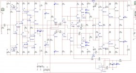
Also tested a slight "improvement" I did, connecting collectors of Q19, Q20 to emitters of Q17, Q18. Looks beautiful, but after that prototype oscillated somewhere above 1MHz, so I just reverted to zeners I used there initially for balancing Vbc of LT-pairs (D8, D9)...
Corrected final schematic is attached.
Attachments
Also tested a slight "improvement" I did, connecting collectors of Q19, Q20 to emitters of Q17, Q18. Looks beautiful, but after that prototype oscillated somewhere above 1MHz, so I just reverted to zeners I used there initially for balancing Vbc of LT-pairs (D8, D9)...
Corrected final schematic is attached.
Looking forward for your listening comments.
Is this output stage the "quad" used by Bryston?
Exactly, it was initially developed by Bryston. In their commercial amplifiers they use more complicated schematic, also including current limiting protection, however this simplified design I use showed excellent performance in many prototypes - like it a lot.
The other one I like a lot - the one with class A drivers (CCS loaded) - see here (Post #16):
Last edited:
I considered converting a quasi output stage to quad. Until one of our experts pointed out that it has an inherent problem with shoot through at HF.
Well, yes... somewhere over 10 MHz... but if you don't go that far - it's very "symmetric" = low distortion.
I killed 2 Sanken transistors experimenting with local "feed forward" - at some point it turned into a "screaming oscillator (c) ostripper" far over 10MHz.
But this simple one is rock stable. If you don't go over 1 MHz - don't worry.
I killed 2 Sanken transistors experimenting with local "feed forward" - at some point it turned into a "screaming oscillator (c) ostripper" far over 10MHz.
But this simple one is rock stable. If you don't go over 1 MHz - don't worry.
I think he was referring to just 100kHz, not 10MHz, nor to oscillation.
The BJTs do not turn off quickly enough after the others have already turned on.
The BJTs do not turn off quickly enough after the others have already turned on.
I tested it live, extensively, with up to 1 MHz signals, up to clipping (with Sanken 2sc2922/2sa1216). Never had any problem. These ones are fast enough.
Any new assembled GainWire mk2?
I would like to hear about listening experience and assembling problems if any.
BR Damir
I would like to hear about listening experience and assembling problems if any.
BR Damir
Hi Damir, just got a call from PCB manufacturing - they will deliver PCBs tomorrow.
Looking forward as well 😉
Looking forward as well 😉
OK, PCB and 1% tolerance resistors, I ordered for this one, are in hand! I will do my best to solder and try it tomorrow. Looking forward 🙂
Almost done!
Just realized I ran out of 0.47uF capacitors... will buy some tomorrow morning
Very nice PCB, looking forward.
Valery, isn't 0.47uF to small value for the DC servo? It could introduce low frequencies distortion if the low frequency corner is not low enough.
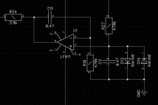
I use 2 of them (non-inverting integrator), so overall capacitance is close to 1uF. Together with 470k + 470k = almost 1M resistor it will be ok
In the GainWire I use the same type DC servo and increase in distortion at 16 Hz is quite big if instead of 2.2 uF I use 0.47 uF, probably because the distortion level is quite lower then in similar power amp, from 6.3 ppm to 17.5 ppm in NGFB mode and from .05 ppm to 1.15 ppm in CFA mode.
Good point - I will look at it a bit closer. Nothing stops us ftom using 1uF + 1uF )
What resistor value did you use?
What resistor value did you use?
- Status
- Not open for further replies.
- Home
- Amplifiers
- Solid State
- No NFB line amp (GainWire mk2)