What would be the ideal voltage for a 4 ohms (in reality more like 3.5 ohms)
Thanks
Do
Valery recommended +/- 40V for a 4 ohm load.
Last edited:
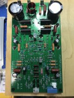
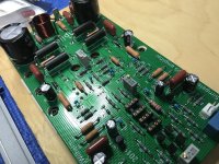
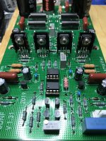
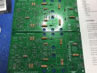
Here's the build so far!
Most resistors are Takman Metal Film and Vishay CPF2 and CPF3.
View attachment 787048
Ciao!
Do
Looking good!
Be careful with soldering the output devices - a couple of resistors are placed between the leads 😉
I finished assembling both modules and started the initial fire up the amplifier (without magic smoke). I'm using a SMPS which outputs +/-39Vdc. Seems like I was getting 14Vdc offset and with max adjustment on R8, I can get to 1.4Vdc... Which is weird... Bias seems to rise properly though and voltage on emitter resistors seem to be all the same, or very close... What do you suggest I try? Is the voltage too low?


Thanks
Do


Thanks
Do
I finished assembling both modules and started the initial fire up the amplifier (without magic smoke). I'm using a SMPS which outputs +/-39Vdc. Seems like I was getting 14Vdc offset and with max adjustment on R8, I can get to 1.4Vdc... Which is weird... Bias seems to rise properly though and voltage on emitter resistors seem to be all the same, or very close... What do you suggest I try? Is the voltage too low?
Thanks
Do
Hi Do,
The offset you see is rather high - do you see the same kind of offset in both channels?
Cheers,
Valery
Yes, same exact behavior. I double checked all transistors again to be in the proper places. When assembling I double check and triple check everything and measure before and after to ensure components are ok. Don't know what is wrong here...
I'll stop any more testing just in case... But no smoke and no components going too hot.
Do
I'll stop any more testing just in case... But no smoke and no components going too hot.
Do
Yes, same exact behavior. I double checked all transistors again to be in the proper places. When assembling I double check and triple check everything and measure before and after to ensure components are ok. Don't know what is wrong here...
I'll stop any more testing just in case... But no smoke and no components going too hot.
Do
OK, I will look into it late in the evening.
I will ask you to measure some things and then we'll see.
For the beginning - can you please measure the voltage across 15V Zeners (1n4744).
Cheers,
Valery
Sounds like the front end isn't getting enough power. A quick and dirty test would be to parallel another 1k resistor on R17 and R18. In normal operation with +/- 48V you would have around 36mA to supply the op amps. With the extra resistors tacked on with +/- 39V rails you would have around 39mA available.
ok, but those are 2W resistors. I'll have to order some 2w 1K resistors or to test I can use 250mW ones?
Otherwise I have some carbon comp Kiwame 2W resistors but I don't think carbon comp is good idea in there...
For testing it doesn't really matter what they are. Anything around 3k will raise the current a bit and hopefully give you a solid +/- 15V
Ooops! Already tested with 1K... Hopefully nothing was damaged!
With 1K paralleled the voltage on D3 and D4 were close to 15.5Vdc but offset was still the same. Is it worth trying 3K resistor?
Do
With 1K paralleled the voltage on D3 and D4 were close to 15.5Vdc but offset was still the same. Is it worth trying 3K resistor?
Do
If the offset was still the same there's other issues. Best wait for Valery to do some simulation.
- Home
- Amplifiers
- Solid State
- No-global-loop amplification

