Ah, now I see what you meant. No, as I mentioned before, Martin's MathCad models don't yet cover curved edges etc -that facility will be added at some point later in the year I believe, once he's upgraded all the existing sheets to this standard. I believe the open-baffle sheet that will be added at the same time covers most of these issues, and will likely form the basis for additions to the others, but not having seen that one yet, I don't know for certain. As I have said, I'm not claiming any of these models are complete designs -they are very far from that; they're just basic, general concepts generated in the sheet for other people to explore and refine, whether through practical experimental construction, or through updates to the worksheets as and when they arrive. Whilst far from finished, they do provide a good basis for people to work upon. And I don't think there are too many people who will be complaining at the accuracy of the new sheets. Perfect? Of course not. Very, very accurate in most situations, and a superb starting place for refinements? Of course. But fine-tuning to a specific room is nothing new, and these give a very good starting point, where before, it was mostly guess-work and luck right from the off.
I assume with the 4ms diffraction pulse you're refering to creating a virtual 2pi radiation space that the wavefront sees -the holy virtual infinite baffle, correct? My own rough and ready test mules had their additional sides (they were a standared set of FE207E MLTLs built according to the design on Martin's site) canted back at a 20 degree angle, and close to a rear wall, I suspect they were coming fairly close to achieving this without needing felt around them, or becoming excessively wide: 1.3m is a bit much, even for me! Can't speak for the room-modes: I haven't really had the opportunity to look into room acoustics yet, but it looks like a minefield to me! One thing at a time!
All the best
Scott
Scottmoose said:Take 1 full-range unit of your favourite type for covering the mid-range and treble. The FE108ESigma for example. Mounted in the sealed upper half of a nice, ... Now add two of your favourite 8" bass units. Mounted magnet to magnet in bipolar configuration.
Exactly... and set the active XO at the BS frequency, a wider baffle gives a lower XO... it even has an acronym -- FAST (don't ask me what it stands for, i still haven't figured that out)
dave
Originally posted by Scottmoose 1.3m is a bit much
My 1.2 m wide OBs were too much for my room (as it is currently organized).
dave
planet10 said:it even has an acronym -- FAST (don't ask me what it stands for, i still haven't figured that out)
First time I saw FAST mentioned it was explained as Fullrange And Subwoofer Technology
What's the problem? I'm working on a set of 6 foot wide OBs as we speak. Do you not have 1.2m or 2.4m?planet10 said:
My 1.2 m wide OBs were too much for my room (as it is currently organized).
dave
Dave
😀
Interesting. And good to know there is merit in some of it too. I'll keep plugging away at different ideas related to these. However, time for a quick, more conventional, narrow-baffle design.
Lynn Olson's Ariel. What a great example of a 'classic' TL. I used to own a pair, and missed them dearly when I sold them on. However, looking back, I think it was Lynn's superb driver selection and crossover design that I missed the most. The cabinet, on the other hand... well, I was wondering if it would be possible to equal or beat it with a cabinet that would be much easier to build, and hopefully provide a bit more bass as well. Is it possible? Well, yes. It looks like it is. No surprise there: the mass-loading technique 9 times out of 10 allows you to go lower, smoother.
Looking at the smoothed measurements on Lynn's site (www.nutshellhifi.com -well worth a visit; I love the blend of art and engineering philosophy), the Ariel cabinet is sub-optimal. Below 100Hz, response plunges. I know Lynn wasn't aiming for bass, but it's a bit much in my view. Below is an anechoic plot for these drivers in an MLTL enclosure:
Attachments
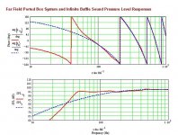
You can flatten the slight rise with 1ohm of series resistance in the hot lead if you like.
All parameters as standard; Sd & Vas doubled as per the procedure outlined on Martin's site, Lvc & Re halved due to the paralleled drivers. I wanted to retain the MTM layout, and Lynn's wonderful crossover, so I've preserved the 8" external width. In fact, external width and depth are identical to the regular Ariel variations on Lynn's site, which was both surprising, and convenient, so external depth is 13 1/2" (these assume 3/4" build material is used). Total line length is 45", external height is 47 1/4" with a base, as I doubled the top panel, just in case. 4" diameter, 2" long port 3" up from the base on the front panel. 0.25lbs ft^3 of stuffing from the top to just below the drivers. Tweeter mounted at 11 1/4" down from internal So. Drivers offset as per those in the existing Ariels. Keep the wide radii to the edges -I doubt they'd do any harm, and they may do some good.
This is a nice, easy build, in contrast to the normal Ariels, which are one of the hardest enclosures to build that you're ever likely to come across. In room prediction, front baffle 27" from the rear wall (for these I will from now on always assume them to be placed 1 cabinet depth away from the rear wall), carpeted floor, near-field listening on axis with the drivers. Not too shabby really.
Cheers
Scott
Attachments

It has been an active day for the thread, my spam folder was full of response notifications when I got home from work. I thought I would like to add a couple of thoughts/answers that address some of the issues discussed above.
Actually, I have quite a few crossover worksheets. These range from the simple ones that assume a perfect filter loaded by a constant resistance to ones that read in measured driver impedances and SPLs and do the circuit analysis using specified caps, resistors, and inductors. The real interesting worksheet reads in the frequency response of the passive filter components and use those when simulating the system response, if you have never measured the impedance of an inductor you should since it will surprise you big time. The problem with most of these worksheets is that they read and write data files which is a function disabled in the MathCad Explorer program.
Both driver size, XO response, and beaming are simulated in my open baffle worksheet when calculating the open baffle response. For a reasonable calculation, one that does not include every possible degree of diffculty and refinement, I think that this approach does a very credible job and gets most of the answer correct. If somebody wants to track every response ripple the calculation approach is probably is not refined enough.
Baffle shapes other then rectangular will come later, but not too exotic since probably 95% of the DIY designs are rectangular or trapezoidal baffles. Curved baffles will not be considered since only a few would really be interested.
Where and why does the fidelity go?
The math I use is definitely reversible. Not sure what math would not allow the reverse calculation from being carried out to reproduce the original transient response.
I guess my goal is to extend the simple T/S style of calculation out beyond the internal box boundarys to include some of the room environment. Including the shape of the front baffle, the position of the driver and any openings, the floor, and the rear wall sort of made sense as a starting point because everybody has these influences effecting the response of their designs. Maybe I need to add a side wall option because most people will also have this boundary. But once it gets beyond these near boundary influences everybody's room is different. So I am trying to elevate the worksheets to be better than other simple design packages that are available for free or a nominal charge. The intent is to make a big step up in the accuracy of the calculations and to keep improving. There will always be something not included or considered that will reduce the accuracy. The user has to determine if this is an acceptable tool.
I believe the worksheet calculates both effects.
Special baffle shapes could be considered, I plan to add a trapezoidal shape for ML TQWT enclosures. Rounded edges or addition of felt is not considered and at present I have no plans to include either.
At present room modes are not included in the worksheet. However, for a few years I have had a room response calculator that simulates rectangular rooms with different floor, wall, and ceiling reflection coefficients and arbitrary speaker and listener positions. At some point this might be the next level of accuracy for a future upgrade to the worksheets.
Hope that clears up a few questions and comments,
Different drivers and XOs have much more impact on the sound in the mid ranges where the vocals are. Pretty complicated such that I doubt Martin would try to model in the near future.
Actually, I have quite a few crossover worksheets. These range from the simple ones that assume a perfect filter loaded by a constant resistance to ones that read in measured driver impedances and SPLs and do the circuit analysis using specified caps, resistors, and inductors. The real interesting worksheet reads in the frequency response of the passive filter components and use those when simulating the system response, if you have never measured the impedance of an inductor you should since it will surprise you big time. The problem with most of these worksheets is that they read and write data files which is a function disabled in the MathCad Explorer program.
The effect of baffle on frequency response also depends on driver size and XO frequency due to beaming effects.
Both driver size, XO response, and beaming are simulated in my open baffle worksheet when calculating the open baffle response. For a reasonable calculation, one that does not include every possible degree of diffculty and refinement, I think that this approach does a very credible job and gets most of the answer correct. If somebody wants to track every response ripple the calculation approach is probably is not refined enough.
Additionally, the 2D shape and the surface curvature also plays a role in the smoothness of the response. These cannot be realistically compensated for without losing fidelity. Most engineers that rely on the FR amplitude response too heavily don't realize this.
Baffle shapes other then rectangular will come later, but not too exotic since probably 95% of the DIY designs are rectangular or trapezoidal baffles. Curved baffles will not be considered since only a few would really be interested.
Where and why does the fidelity go?
I'm not a math wizard, but I think that the math used to generate FR from transient data is not reversible. Therefore the same FR response can result from different transient data, but the different data will sound differentl while showing the same FR response.
The math I use is definitely reversible. Not sure what math would not allow the reverse calculation from being carried out to reproduce the original transient response.
Are you suggesting that Martin's MathCad models are inaccurate because they only work at present assuming a flat baffle, with no curves, backward folds etc? Watch this space if that is the case -I believe these features will be emerging in due course. Or that the frequency response plots they generate is based purely upon the amplitude of the driver and port output, and does not account for anything else such as reflections, and their own effect upon it? I don't know enough of the math or parameters behind the sheets to comment I'm afraid -Martin -over to you!
I guess my goal is to extend the simple T/S style of calculation out beyond the internal box boundarys to include some of the room environment. Including the shape of the front baffle, the position of the driver and any openings, the floor, and the rear wall sort of made sense as a starting point because everybody has these influences effecting the response of their designs. Maybe I need to add a side wall option because most people will also have this boundary. But once it gets beyond these near boundary influences everybody's room is different. So I am trying to elevate the worksheets to be better than other simple design packages that are available for free or a nominal charge. The intent is to make a big step up in the accuracy of the calculations and to keep improving. There will always be something not included or considered that will reduce the accuracy. The user has to determine if this is an acceptable tool.
There are two aspects of baffle design. One is the radiation space, and the other is the additional transient wave caused by sudden lose of support as the wave reaches the edge. The former is considered mostly, and thus the BSC. The latter normally is less considered, and cannot be acurately compensated for electrically.
I believe the worksheet calculates both effects.
Another approach is to design round baffle edges, design special baffle shape, or add felt around the drivers in order to spread the lose of baffle support over time. I believe Martins Worksheets may not handle the later approach.
Special baffle shapes could be considered, I plan to add a trapezoidal shape for ML TQWT enclosures. Rounded edges or addition of felt is not considered and at present I have no plans to include either.
To solve the radiation space issue, I think it's a more simple problem. But you also need to consider first without the room modes, so that you get the right transient wave front, but then there is a tradeoff between the room modes and maintaining the correct transient wave front energy. This is where both need to be considered separately and not just looking at the frequency response charts.
At present room modes are not included in the worksheet. However, for a few years I have had a room response calculator that simulates rectangular rooms with different floor, wall, and ceiling reflection coefficients and arbitrary speaker and listener positions. At some point this might be the next level of accuracy for a future upgrade to the worksheets.
Hope that clears up a few questions and comments,
Could the room simlations include a stairway or stairwell?
I don't think so. Right now they consider only a closed rectangular room without any furniture.
Martin
If you make it too good you will spoil all the fun 🙂
And there willl be nothing to argue about!
😀
If you make it too good you will spoil all the fun 🙂
And there willl be nothing to argue about!
😀
Well guys, there you have it. I did say don't underestimate Martin didn't I?
In my own experience, his latest worksheet is the most accurate and capable speaker design tool I have ever seen, and is a quantum leap forward over anything that has been around before, which is primarily what this thread is about, and demonstrating some of the different designs it will allow us to explore more thoroughly.
Cheers for now
Scott
I know you're speaking facetiously, and I take it in the spirit that it's intended! However (time to nail my colours to the mast) I make no apologies for my partisan suport of Martin and his work. I have no agenda here, other than to tell you what I find as honestly and as accurately as possible. I stand to gain nothing, though like many I value his advice and friendship, and enjoy our email discussions. As far as I am concerned I owe Martin my support thanks to the major benefits his work has brought to my system, and my enjoyment of music.
He was the first person to accurately model the quarter-wave resonator, despite many people trying to do just that for at least the last three decades, with effectively zero success. To say that is important is an understatement. What makes it really unique is that he then decided to put all of his research up, on the internet, for the benefit of the DIY community to study and use to create their own designs. To cap it all, he is always willing to dispense advice, often of a highly technical nature to anyone who asks. Does he recieve any recognition for these achievements and this amazingly generous contribution by the wider audio press or the 'regular' designers? Does he blazes, despite (and probably because of) the fact that he is actually ahead of them 95% of the time. The first time he was mentioned in the audio magazines in Europe, insofar as I know, was when I fired a letter off to Hifi World about the worksheets and TLs in general that was printed only a couple of months back, despite the worksheets being around for several years.
You know what really, and I mean really hacks me off? The people, if you can use such a term, though reptiles might be more appropriate, who have deliberately taken advantage of his hard work. That's happened in two ways so far: for commercial gain, without taking a licence for using the worksheets for that purpose (it is made clear on his site that a licence should be paid if they are to be used for designing commercial speakers). Worse still are those loathsome little termites who have, in effect, decided to steal his work, and pass it off as their own. Perhaps it is not their fault, and they are suffering from delusions brought on by mental illness etc. Naturally 'their' papers are treated as 'revolutionary', 'groundbreaking' 'unique' and the like, and regularly appear in the wider audio print. He's had to hold off from making any upgrades for the sheets available for quite a while now, because of this, and, not without some heart-searching I'm sure, has eventually decided he is going to have to charge a modest fee for the upgraded sheets. I don't blame him, and neither does anyone else: at least that way he'll see some modest compensation for eveything he's done for us all. Some might say he was overly idealistic if he expected people to be honest. He probably was. But the evil eye should be directed toward the thieves, not to him.
In return, we get the most accurate simulation program I've ever seen (and I've seen most of them), with a heck of a lot more still to come. Is it perfect? Of course not, nothing is, and no-one claimed it was, but it's very good indeed and will allow people to develop their own setups to a level they might never otherwise achieve. If that isn't worth shouting about, nothing is.
Scott,
Your use of the Ariel as an example is particularly appealing to me. I made the ME2 version several years back. One of the reasons was the complexity of the Ariel cabinets. Conversion to a MLTL is likely in my future.
Thanks
Your use of the Ariel as an example is particularly appealing to me. I made the ME2 version several years back. One of the reasons was the complexity of the Ariel cabinets. Conversion to a MLTL is likely in my future.
Thanks
Well said Scott!
I could not agree more with your thoughts on the work Martin has put out in the public domain. I believe that through his efforts the design of good quality loudspeakers will be no longer a secret squirrel business where profit hunger companies can charge ridiculous amounts.
The result is that more people will be able to enjoy listening to affordable quality music. The results is a bigger DIY audio family which results in new ideas and better designs. Things begin to grow and develop very quickly.
You see it becomes a positive all good scenario.
Yes there are scumbags in the world. Let’s try not to focus more energy on them than they deserve.
Scott
Agreed. And rant over -sorry about that guys! Time to look to the positive aspects, like what we can do with this new sheet...
Ed -good choice with the ME2. Great bookshelf, superb drivers and crossover. They'll do very well in an MLTL. Might be worth with this one actually not using stuffing, but taking a leaf out of Bob Brines' book, and lining the top and rear baffle of the cabinet with stiff acoustic fibreglass.
The Ariel, as it stands, is a bit of an odd one, and it's not easy (and perhaps, at present, not even possible) to model accurately, thanks to the independent lines having different values, which I assume means that they could be differentially tuned. If anyone knows one way or the other, I'd love to hear, as this is an aspect of TL design I have not looked into. One thing I'm sure of however: in terms of a flat freqency response at the least, to say nothing of ease of construction, the MLTL version will beat it, and should add more bass-weight into the bargain. I've looked some more into that possibility: the shallow dip in the response around 100Hz can be largely flattened by pulling them back 6" toward the rear wall, which will still keep them a reasonable distance away, so the imaging should not be impaired.
If anyone is interested :
http://cgi.ebay.com/Mathcad-2000-Pr...goryZ182QQssPageNameZWDVWQQrdZ1QQcmdZViewItem
This is probably one of the best versions of MathCad. Stable and great interface. Comes with Smartsketch the software I use to do all of my drawings.
I have absolutely no connection with the seller.
http://cgi.ebay.com/Mathcad-2000-Pr...goryZ182QQssPageNameZWDVWQQrdZ1QQcmdZViewItem
This is probably one of the best versions of MathCad. Stable and great interface. Comes with Smartsketch the software I use to do all of my drawings.
I have absolutely no connection with the seller.
Scott,
I've always been a big supported of Martin's work.
Are you aware of any comparison between measured results and sims using the sheets, for MLTLs, that you could point towards? I spent many years searching for reliable thermodynamic data for various speaker stuffings, and have been left with contradictory results from several otherwise reliable sources.
Martin and I discussed this two years ago, with Martin continuing on but no real conclusion reached.
I would still love to see data correlating the MLTL models with measured results. This would be key to validating the stuffing models used. You mention the accuracy of the sheets, so I was hoping you had some leads. My interest is more in the stuffing properties assumed, than the sheets themselves, which are proven in assuming good data.
Dave
- Status
- Not open for further replies.
- Home
- Loudspeakers
- Full Range
- New version of Martin King's MathCad Worksheets is coming soon!