Questions for XRK, TB46 , JAG or any other Akabak users
Also , another quick question for any Akabak users ..... Does Akabak have any function that adds up the volume total for all vents/ducts/waveguides .... Just wanted to double check to make sure i am not going oversize or undersize with these modified scripts ...
I have improved upon my cobbled together 9 part K-aperture by adding 1.19cm depth to the aperture's radiators, it is just under a half inch of depth but it added radiation resistance, the loading has increased and it shifted FB down a small amount.... Midrange is not as smooth but i think this might be a more accurate representation of what i will actually measure when built ...
The aperture code as it looks now:
|---------------------------------------------
| The Aperture:
|(in this case the classic K-aperture,type #1)
|---------------------------------------------
| This first set of code defines the front chamber
|(behind the aperture and in front of the baffle)
| from top to bottom
|---------------------------------------------------

Duct 'P6' Node=4=8
WD=31.9cm
HD=9cm
Len=6.66cm
Visc=1

Duct 'P7' Node=8=9
WD=31.9cm
HD=8cm
Len=6.66cm
Visc=1

Duct 'P8' Node=9=10
WD=31.9cm
HD=7cm
Len=6.66cm
Visc=1

Duct 'P9' Node=10=11
WD=31.9cm
HD=6cm
Len=6.66cm
Visc=1

Duct 'P10' Node=11=12
WD=31.9cm
HD=5cm
Len=6.66cm
Visc=1

Duct 'P11' Node=12=13
WD=31.9cm
HD=4cm
Len=6.66cm
Visc=1

Duct 'P12' Node=13=14
WD=31.9cm
HD=3cm
Len=6.66cm
Visc=1

Duct 'P13' Node=14=15
WD=31.9cm
HD=2cm
Len=6.66cm
Visc=1

Duct 'P14' Node=15=16
WD=31.9cm
HD=1cm
Len=6.66cm
Visc=1

|--------------------------------------------------------------------
|The following code defines the dadiators (K-aperture in multiple parts)
| series tuned
|--------------------------------------------------------------------


Radiator 'Rad_P6' Node=8 |CSA=19.98sq cm
WD=3cm
HD=6.66cm
DD=1.19cm
x=0 y=28cm z=0 HAngle=0 VAngle=0

Radiator 'Rad_P7' Node=9 |CSA=26.64sq cm
WD=4cm
HD=6.66cm
DD=1.19cm
x=0 y=21.33cm z=0 HAngle=0 VAngle=0

Radiator 'Rad_P8' Node=10 |CSA=33.3sq cm
WD=5cm
HD=6.66cm
DD=1.19cm
x=0 y=15cm z=0 HAngle=0 VAngle=0

Radiator 'Rad_P9' Node=11 |CSA=39.96sq cm
WD=6cm
HD=6.66cm
DD=1.19cm
x=0 y=8.33cm z=0 HAngle=0 VAngle=0

Radiator 'Rad_P10' Node=12 |CSA=66.6sq cm
WD=10cm
HD=6.66cm
DD=1.19cm
x=0 y=0 z=0 HAngle=0 VAngle=0

Radiator 'Rad_P11' Node=13 |CSA=119.88sq cm
WD=18cm
HD=6.66cm
DD=1.19cm
x=0 y=-8.33cm z=0 HAngle=0 VAngle=0

Radiator 'Rad_P12' Node=14 |CSA=159.84sq cm
WD=24cm
HD=6.66cm
DD=1.19cm
x=0 y=-15cm z=0 HAngle=0 VAngle=0

Radiator 'Rad_P13' Node=15 |CSA=186.48sq cm
WD=28cm
HD=6.66cm
DD=1.19cm
x=0 y=-21.33cm z=0 HAngle=0 VAngle=0

Radiator 'Rad_P14' Node=16 |CSA=212.454sq cm
WD=31.9cm
HD=6.66cm
DD=1.19cm
x=0 y=-28cm z=0 HAngle=0 VAngle=0


|Total Aperture CSA=865.134sq cm
Also , another quick question for any Akabak users ..... Does Akabak have any function that adds up the volume total for all vents/ducts/waveguides .... Just wanted to double check to make sure i am not going oversize or undersize with these modified scripts ...
I have improved upon my cobbled together 9 part K-aperture by adding 1.19cm depth to the aperture's radiators, it is just under a half inch of depth but it added radiation resistance, the loading has increased and it shifted FB down a small amount.... Midrange is not as smooth but i think this might be a more accurate representation of what i will actually measure when built ...
The aperture code as it looks now:
|---------------------------------------------
| The Aperture:
|(in this case the classic K-aperture,type #1)
|---------------------------------------------
| This first set of code defines the front chamber
|(behind the aperture and in front of the baffle)
| from top to bottom
|---------------------------------------------------
Duct 'P6' Node=4=8
WD=31.9cm
HD=9cm
Len=6.66cm
Visc=1
Duct 'P7' Node=8=9
WD=31.9cm
HD=8cm
Len=6.66cm
Visc=1
Duct 'P8' Node=9=10
WD=31.9cm
HD=7cm
Len=6.66cm
Visc=1
Duct 'P9' Node=10=11
WD=31.9cm
HD=6cm
Len=6.66cm
Visc=1
Duct 'P10' Node=11=12
WD=31.9cm
HD=5cm
Len=6.66cm
Visc=1
Duct 'P11' Node=12=13
WD=31.9cm
HD=4cm
Len=6.66cm
Visc=1
Duct 'P12' Node=13=14
WD=31.9cm
HD=3cm
Len=6.66cm
Visc=1
Duct 'P13' Node=14=15
WD=31.9cm
HD=2cm
Len=6.66cm
Visc=1
Duct 'P14' Node=15=16
WD=31.9cm
HD=1cm
Len=6.66cm
Visc=1
|--------------------------------------------------------------------
|The following code defines the dadiators (K-aperture in multiple parts)
| series tuned
|--------------------------------------------------------------------
Radiator 'Rad_P6' Node=8 |CSA=19.98sq cm
WD=3cm
HD=6.66cm
DD=1.19cm
x=0 y=28cm z=0 HAngle=0 VAngle=0
Radiator 'Rad_P7' Node=9 |CSA=26.64sq cm
WD=4cm
HD=6.66cm
DD=1.19cm
x=0 y=21.33cm z=0 HAngle=0 VAngle=0
Radiator 'Rad_P8' Node=10 |CSA=33.3sq cm
WD=5cm
HD=6.66cm
DD=1.19cm
x=0 y=15cm z=0 HAngle=0 VAngle=0
Radiator 'Rad_P9' Node=11 |CSA=39.96sq cm
WD=6cm
HD=6.66cm
DD=1.19cm
x=0 y=8.33cm z=0 HAngle=0 VAngle=0
Radiator 'Rad_P10' Node=12 |CSA=66.6sq cm
WD=10cm
HD=6.66cm
DD=1.19cm
x=0 y=0 z=0 HAngle=0 VAngle=0
Radiator 'Rad_P11' Node=13 |CSA=119.88sq cm
WD=18cm
HD=6.66cm
DD=1.19cm
x=0 y=-8.33cm z=0 HAngle=0 VAngle=0
Radiator 'Rad_P12' Node=14 |CSA=159.84sq cm
WD=24cm
HD=6.66cm
DD=1.19cm
x=0 y=-15cm z=0 HAngle=0 VAngle=0
Radiator 'Rad_P13' Node=15 |CSA=186.48sq cm
WD=28cm
HD=6.66cm
DD=1.19cm
x=0 y=-21.33cm z=0 HAngle=0 VAngle=0
Radiator 'Rad_P14' Node=16 |CSA=212.454sq cm
WD=31.9cm
HD=6.66cm
DD=1.19cm
x=0 y=-28cm z=0 HAngle=0 VAngle=0
|Total Aperture CSA=865.134sq cm
Last edited:
correction
I was posting hastily and forgot my punctuation!
It was supposed to say: "Does Akabak have any function that adds up the volume total for all vents/ducts/waveguides?"
ok, thats better
I was posting hastily and forgot my punctuation!
It was supposed to say: "Does Akabak have any function that adds up the volume total for all vents/ducts/waveguides?"
ok, thats better
I was posting hastily and forgot my punctuation!
It was supposed to say: "Does Akabak have any function that adds up the volume total for all vents/ducts/waveguides?"
ok, thats better
I don't think so but I've still never gotten around to reading the manual so...
"Does Akabak have any function that adds up the volume total for all vents/ducts/waveguides?"
I have looked hard and unfortunately, I don't think it does. As Akabak is script based and you enter all elements yourself, you should know what the volume is for the segments you enter. One way is to use a spreadsheet to specify your CSA, and lengths for ducts and waveguides, as a table to help assist you to enter the elements in Akabak and then use the spreadsheet to calculate volume yourself. This is how I do it for complex geometries like 20 segment folded tapped horns.
MMJ, note that if you use the "#" button at the top, it lets you put code in a nice scrollable window without making the actual post super long.
For example, your script from above can be displayed as:
Code:
|---------------------------------------------
| The Aperture:
|(in this case the classic K-aperture,type #1)
|---------------------------------------------
| This first set of code defines the front chamber
|(behind the aperture and in front of the baffle)
| from top to bottom
|---------------------------------------------------
Duct 'P6' Node=4=8
WD=31.9cm
HD=9cm
Len=6.66cm
Visc=1
Duct 'P7' Node=8=9
WD=31.9cm
HD=8cm
Len=6.66cm
Visc=1
Duct 'P8' Node=9=10
WD=31.9cm
HD=7cm
Len=6.66cm
Visc=1
Duct 'P9' Node=10=11
WD=31.9cm
HD=6cm
Len=6.66cm
Visc=1
Duct 'P10' Node=11=12
WD=31.9cm
HD=5cm
Len=6.66cm
Visc=1
Duct 'P11' Node=12=13
WD=31.9cm
HD=4cm
Len=6.66cm
Visc=1
Duct 'P12' Node=13=14
WD=31.9cm
HD=3cm
Len=6.66cm
Visc=1
Duct 'P13' Node=14=15
WD=31.9cm
HD=2cm
Len=6.66cm
Visc=1
Duct 'P14' Node=15=16
WD=31.9cm
HD=1cm
Len=6.66cm
Visc=1
|--------------------------------------------------------------------
|The following code defines the dadiators (K-aperture in multiple parts)
| series tuned
|--------------------------------------------------------------------
Radiator 'Rad_P6' Node=8 |CSA=19.98sq cm
WD=3cm
HD=6.66cm
DD=1.19cm
x=0 y=28cm z=0 HAngle=0 VAngle=0
Radiator 'Rad_P7' Node=9 |CSA=26.64sq cm
WD=4cm
HD=6.66cm
DD=1.19cm
x=0 y=21.33cm z=0 HAngle=0 VAngle=0
Radiator 'Rad_P8' Node=10 |CSA=33.3sq cm
WD=5cm
HD=6.66cm
DD=1.19cm
x=0 y=15cm z=0 HAngle=0 VAngle=0
Radiator 'Rad_P9' Node=11 |CSA=39.96sq cm
WD=6cm
HD=6.66cm
DD=1.19cm
x=0 y=8.33cm z=0 HAngle=0 VAngle=0
Radiator 'Rad_P10' Node=12 |CSA=66.6sq cm
WD=10cm
HD=6.66cm
DD=1.19cm
x=0 y=0 z=0 HAngle=0 VAngle=0
Radiator 'Rad_P11' Node=13 |CSA=119.88sq cm
WD=18cm
HD=6.66cm
DD=1.19cm
x=0 y=-8.33cm z=0 HAngle=0 VAngle=0
Radiator 'Rad_P12' Node=14 |CSA=159.84sq cm
WD=24cm
HD=6.66cm
DD=1.19cm
x=0 y=-15cm z=0 HAngle=0 VAngle=0
Radiator 'Rad_P13' Node=15 |CSA=186.48sq cm
WD=28cm
HD=6.66cm
DD=1.19cm
x=0 y=-21.33cm z=0 HAngle=0 VAngle=0
Radiator 'Rad_P14' Node=16 |CSA=212.454sq cm
WD=31.9cm
HD=6.66cm
DD=1.19cm
x=0 y=-28cm z=0 HAngle=0 VAngle=0
|Total Aperture CSA=865.134sq cmAperture remix
XRK & Jag
Ok, I was unable to find any volume summing function either, but it is ok because most of the boxes i am making in Akabak right now are pretty simple and it is easy enough to figure out the volumes .... For more complex designs i will work out a spreadsheet as you suggested ...
I spent some time today experimenting with the K-aperture code and soon figured out that when i was changing the total CSA (of all parts) i wasn't seeing nearly enough shift in FB or altered response curves which indicated to me that it wasn't emulating the mouth/aperture/Terminus properly ........ hmmmmm 
After some contemplation, a distraction, a smoke break, contemplation , a snack, more contemplation, and some gardening I finally figured out how to improve this K-aperture code , had to add some lines to effectively tie the 9 front chamber sections to the 9 radiators via 9 * .469" long ducts with the same height/width dimensions as the radiators and finally it now seems to react to changes in CSA like you would expect .........
It really does seem to increase damping, decreases excursion a little , which is exciting to see since those are classic characteristics of a Karlson cabinet right?
I noticed that less "stuffing" is now required, and response is more damped , the effects of the driver's offset seem to have shifted too .... This is all very interesting ...
Here is the updated Aperture code (and XRK i tried to use the # feature before as you had recommended a while ago, i just wasn't applying it correctly, thanks for the example, now i understand😀) :
I have looked hard and unfortunately, I don't think it does. As Akabak is script based and you enter all elements yourself, you should know what the volume is for the segments you enter.
MMJ, note that if you use the "#" button at the top, it lets you put code in a nice scrollable window without making the actual post super long.
XRK & Jag
Ok, I was unable to find any volume summing function either, but it is ok because most of the boxes i am making in Akabak right now are pretty simple and it is easy enough to figure out the volumes .... For more complex designs i will work out a spreadsheet as you suggested ...
I spent some time today experimenting with the K-aperture code and soon figured out that when i was changing the total CSA (of all parts) i wasn't seeing nearly enough shift in FB or altered response curves which indicated to me that it wasn't emulating the mouth/aperture/Terminus properly
........ hmmmmm After some contemplation, a distraction, a smoke break, contemplation
, a snack, more contemplation, and some gardening I finally figured out how to improve this K-aperture code , had to add some lines to effectively tie the 9 front chamber sections to the 9 radiators via 9 * .469" long ducts with the same height/width dimensions as the radiators and finally it now seems to react to changes in CSA like you would expect ......... It really does seem to increase damping, decreases excursion a little , which is exciting to see since those are classic characteristics of a Karlson cabinet right?
I noticed that less "stuffing" is now required, and response is more damped , the effects of the driver's offset seem to have shifted too .... This is all very interesting ...
Here is the updated Aperture code (and XRK i tried to use the # feature before as you had recommended a while ago, i just wasn't applying it correctly, thanks for the example, now i understand😀) :
Code:
|---------------------------------------------
| The Aperture:
|(in this case the classic K-aperture,type #1)
|---------------------------------------------
| This first set of code defines the front chamber
|(behind the aperture and in front of the baffle)
| from top to bottom
|---------------------------------------------------

Duct 'P6' Node=11=12
WD=31.9cm
HD=9cm
Len=6.66cm
Visc=1

Duct 'P7' Node=12=13
WD=31.9cm
HD=8cm
Len=6.66cm
Visc=1

Duct 'P8' Node=13=14
WD=31.9cm
HD=7cm
Len=6.66cm
Visc=1

Duct 'P9' Node=14=15
WD=31.9cm
HD=6cm
Len=6.66cm
Visc=1

Duct 'P10' Node=15=16
WD=31.9cm
HD=5cm
Len=6.66cm
Visc=1

Duct 'P11' Node=16=17
WD=31.9cm
HD=4cm
Len=6.66cm
Visc=1

Duct 'P12' Node=17=18
WD=31.9cm
HD=3cm
Len=6.66cm
Visc=1

Duct 'P13' Node=18=19
WD=31.9cm
HD=2cm
Len=6.66cm
Visc=1

Duct 'P14' Node=19=20
WD=31.9cm
HD=1cm
Len=6.66cm
Visc=1

|---------------------------------------------------------------------
|The following code defines the gap and the depth of the K-aperture
|itself (front panel) split into 9 parts.
|Add a pipe character in front of Duct's code line to close off that part
|of the aperture in simulation
|---------------------------------------------------------------------

|Duct 'P15' Node=12=22
WD=3cm
HD=6.66cm
Len=1.19cm
Visc=1

Duct 'P16' Node=13=23
WD=3cm
HD=6.66cm
Len=1.19cm
Visc=1

Duct 'P17' Node=14=24
WD=4cm
HD=6.66cm
Len=1.19cm
Visc=1

Duct 'P18' Node=15=25
WD=5cm
HD=6.66cm
Len=1.19cm
Visc=1

Duct 'P19' Node=16=26
WD=6cm
HD=6.66cm
Len=1.19cm
Visc=1

Duct 'P20' Node=17=27
WD=10cm
HD=6.66cm
Len=1.19cm
Visc=1

Duct 'P21' Node=18=28
WD=20cm
HD=6.66cm
Len=1.19cm
Visc=1

Duct 'P22' Node=19=29
WD=28cm
HD=6.66cm
Len=1.19cm
Visc=1

Duct 'P23' Node=20=30
WD=31.9cm
HD=6.66cm
Len=1.19cm
Visc=1

|--------------------------------------------------------------------
|The following code defines the radiator's dimensions and their positions
|(K-aperture in multiple parts)series tuned
|--------------------------------------------------------------------


Radiator 'Rad_P15' Node=22            |CSA=19.98sq cm
WD=3cm
HD=6.66cm
x=0 y=28cm z=0 HAngle=0 VAngle=0

Radiator 'Rad_P16' Node=23            |CSA=19.98sq cm
WD=3cm
HD=6.66cm
x=0 y=21.33cm z=0 HAngle=0 VAngle=0

Radiator 'Rad_P17' Node=24           |CSA=26.64sq cm
WD=4cm
HD=6.66cm
x=0 y=15cm z=0 HAngle=0 VAngle=0

Radiator 'Rad_P18' Node=25           |CSA=33.3sq cm
WD=5cm
HD=6.66cm
x=0 y=8.33cm z=0 HAngle=0 VAngle=0

Radiator 'Rad_P19' Node=26          |CSA=39.96sq cm
WD=6cm
HD=6.66cm
x=0 y=0 z=0 HAngle=0 VAngle=0

Radiator 'Rad_P20' Node=27          |CSA=66.6sq cm
WD=10cm
HD=6.66cm
x=0 y=-8.33cm z=0 HAngle=0 VAngle=0

Radiator 'Rad_P21' Node=28          |CSA=133.2sq cm
WD=20cm
HD=6.66cm
x=0 y=-15cm z=0 HAngle=0 VAngle=0

Radiator 'Rad_P22' Node=29          |CSA=186.48sq cm
WD=28cm
HD=6.66cm
x=0 y=-21.33cm z=0 HAngle=0 VAngle=0

Radiator 'Rad_P23' Node=30          |CSA=212.454sq cm
WD=31.9cm
HD=6.66cm
x=0 y=-28cm z=0 HAngle=0 VAngle=0


                                         |Total Aperture CSA=738.534sq cm
Last edited:
MMJ,
Yes, good thing you noticed it was not behaving properly with adjustments. Yes, you need very short ducts with same cros sectional area and shape as the radiators. Isn't cool how it can alter the response? I linked the aperture profile to a quadratic curve and can play with aperture shape and initial slot width vs cusp and it all impacts bass extension and smoothness. It is very different from a plain round hole or rectangular hole.
Yes, good thing you noticed it was not behaving properly with adjustments. Yes, you need very short ducts with same cros sectional area and shape as the radiators. Isn't cool how it can alter the response? I linked the aperture profile to a quadratic curve and can play with aperture shape and initial slot width vs cusp and it all impacts bass extension and smoothness. It is very different from a plain round hole or rectangular hole.
ap chat
Yes, right , that's how i did it this time (with the 9 mini ports, but have you found a way to automate changing the curve? or do you still adjust each part manually?) , it definitely behaves differently than a standard round or rectangular mouth ... Cool stuff!
I have noticed that it seems to have an effect similar to increasing the offset but only by about 5 or 10cm (i compensated by reducing offset) .. The aperture loading does seem to add a small amount of cone control too ...... Also seems like it might hammer down the peak around FB that some driver's have in these sims , the increased damping could also turn a flat response into a very wide slightly overdamped hump with a smooth & natural sounding roll-off unless the box is made a little larger (with the benefit of more output)....
I tried both a laid back baffle and straight baffle, and the difference isn't huge, it seems that either way could work but a laid back baffle may help everything fit better physically in some cases..
Anyway , these are just my initial observations .... Things could change as i explore this further ....
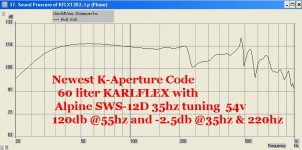
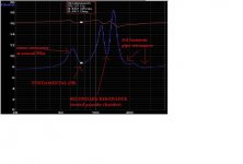
I slapped the new Aperture onto the Alpine SWS12d simulation to try it out and experiment ...I attached a response graph to this post... Looks like it works well, the bandwidth is limited to about 220hz but that is just the nature of that driver, it is not meant to be a midbass device and 220hz is actually pretty good in this case .... You can see the resonance of the front chamber and aperture attempting to create some sort of output around 450-700hz but it is not consistent enough to be useful ........ This is with an aperture CSA of just over 700cm2 so perhaps i could reduce the CSA and shift that upper resonance downward making it more useful for this particular cab...
Decent output for a 60 liter box 😀 , and really not terribly different from the guesswork sims we were doing with Hornresponse, but this is a nice way to verify that work 🙂 According to these results i am thinking the LAB15-4 should also look pretty good in the 90 liter Karlflex. but i will try it out to be sure ..
MMJ,
Yes, good thing you noticed it was not behaving properly with adjustments. Yes, you need very short ducts with same cros sectional area and shape as the radiators. Isn't cool how it can alter the response? I linked the aperture profile to a quadratic curve and can play with aperture shape and initial slot width vs cusp and it all impacts bass extension and smoothness. It is very different from a plain round hole or rectangular hole.
Yes, right , that's how i did it this time (with the 9 mini ports, but have you found a way to automate changing the curve? or do you still adjust each part manually?) , it definitely behaves differently than a standard round or rectangular mouth ... Cool stuff!
I have noticed that it seems to have an effect similar to increasing the offset but only by about 5 or 10cm (i compensated by reducing offset) .. The aperture loading does seem to add a small amount of cone control too ...... Also seems like it might hammer down the peak around FB that some driver's have in these sims , the increased damping could also turn a flat response into a very wide slightly overdamped hump with a smooth & natural sounding roll-off unless the box is made a little larger (with the benefit of more output)....
I tried both a laid back baffle and straight baffle, and the difference isn't huge, it seems that either way could work but a laid back baffle may help everything fit better physically in some cases..
Anyway , these are just my initial observations .... Things could change as i explore this further ....
I slapped the new Aperture onto the Alpine SWS12d simulation to try it out and experiment ...I attached a response graph to this post... Looks like it works well, the bandwidth is limited to about 220hz but that is just the nature of that driver, it is not meant to be a midbass device and 220hz is actually pretty good in this case .... You can see the resonance of the front chamber and aperture attempting to create some sort of output around 450-700hz but it is not consistent enough to be useful ........ This is with an aperture CSA of just over 700cm2 so perhaps i could reduce the CSA and shift that upper resonance downward making it more useful for this particular cab...
Decent output for a 60 liter box 😀 , and really not terribly different from the guesswork sims we were doing with Hornresponse, but this is a nice way to verify that work 🙂 According to these results i am thinking the LAB15-4 should also look pretty good in the 90 liter Karlflex. but i will try it out to be sure ..
Attachments
Last edited:
MJM,
Nice work there - the 220Hz and the shape of the falloff seems about right - playing with the aperture's profile can change this. What I found is if the aperture starts small (like a cusp) and expands following the Karlson profile scaled to the length and width needed it can smooth it out pretty well. If the profile starts with a finite slot width you get higher SPL output but at the expense of more peakyness.
I described how I automated it in the Karlson thread. Basically I curve fit the Karlson profile into a parabolic non dimensional unit function that goes smoothly from 0 to 1 for an input of 0 to 1. Use that function multiplied by desired aperture width. The input variable is distance along aperture from small end. Use real aperture distance divided by total aperture height to get non dimensional height as input into function. Use that function to set, automatically, via equations, all the radiator sizes (Width and Height and x & y position) along the aperture length. Then you have one master equation that controls the profile. If you modify that equation it can change the profile shape or whether or not you have a cusp or a slot. It's a lot equations but if you use a recursive programming structure you can copy and paste and modify the indices.
Hope that helps.
Last edited:
XRK, do you think a pair of Tang Band W5-1138SMF 5-1/4" Paper Cone Subwoofers would work in this sub design? Due to WAF and space considerations, this one needs to be less than 8" high, though it can be pretty wide (20 and some inches) and up to 11" deep.
HAPPY HOLIDAY!
Hey all !
Happy Easter!
A hollow chocolate bunny represents the void within all of us that can be filled with obscure DIY speakers along with other wonderfully nerdy things, and to a lesser extent booze and women .....
hehehe
ok , just kidding .. ... Kinda 😉
Hey all !
Happy Easter!
A hollow chocolate bunny represents the void within all of us that can be filled with obscure DIY speakers along with other wonderfully nerdy things, and to a lesser extent booze and women .....
hehehe
ok , just kidding .. ... Kinda 😉
XRK, do you think a pair of Tang Band W5-1138SMF 5-1/4" Paper Cone Subwoofers would work in this sub design? Due to WAF and space considerations, this one needs to be less than 8" high, though it can be pretty wide (20 and some inches) and up to 11" deep.
Doug ,
Mr XRK has come up with some great little mini subs based upon this same sort of K-technology , check out his XKi sub discussion:
http://www.diyaudio.com/forums/full-range/268524-xki-xs-ab-initio-karlson-6th-order-bandpass.html
I am working on a simplified version of my tri-chamber K cab that looks like it might have potential for smaller drivers, but right now it is scaled up for a 12" Dayton ...
X , You might find this interesting
XRK,
Ok , i am trying out cusp versus slot style apertures and it does change things a bit .... Pipe harmonics still seem to create some interference with bumps & dips in the midrange response but i am curious to see how similar the real world measurements look ... Do you notice some midrange discrepancy between your simulated K-boxes and their measured response?
I will read through the Karlson thread in order to try to better understand what you are describing here ..... I have managed to link the dimensions of the K-ap ports to the radiators using the "DEF=" command which speeds up the process of adjusting the aperture contours and areas, but i have a way to go before tying everything into a master equation ...
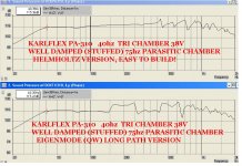
But hey , XRK, I did figure out something intriguing yesterday that might be of interest to you since you build K-subs with smaller drivers .... I am able to get (according to sim) the same output and excursion control from a simplified (more helmholtz based) tri-chamber Karlflex type cab (Like a DCR-Kcab hybrid) compared to a Tri-chamber Karlflex with long path (eigenmode version) ....... Not sure if i believe it since i have always had better luck getting satisfying low-end with quarter wave loaded cabs, but this is so simple and easy to scale down for small drivers that it is very tempting.
The parasitic chamber is well damped (using stuffing) on this cabinet tuned to between 1.6 and 1.9x fundamental and it reduces excursion by 2mm on the PA-310 which allows 38v input (instead of 28v) while still staying within the safe physical range for that driver ... Along with the extra 30 liters of cabinet size gives me an additional 4db output according to Akabak! 😀 This is a great thing for a driver that has so much thermal power handling yet so little physical capability ..... Might be something that could be useful for an XKi type box with drivers that like this Dayton have plenty of electrical power handling yet low xmax 🙂
Both sims here are using the "cusp" style K-aperture ...
MJM,
Nice work there - the 220Hz and the shape of the falloff seems about right - playing with the aperture's profile can change this. What I found is if the aperture starts small (like a cusp) and expands following the Karlson profile scaled to the length and width needed it can smooth it out pretty well. If the profile starts with a finite slot width you get higher SPL output but at the expense of more peakyness.
XRK,
Ok , i am trying out cusp versus slot style apertures and it does change things a bit .... Pipe harmonics still seem to create some interference with bumps & dips in the midrange response but i am curious to see how similar the real world measurements look ... Do you notice some midrange discrepancy between your simulated K-boxes and their measured response?
I described how I automated it in the Karlson thread. Basically I curve fit the Karlson profile into a parabolic non dimensional unit function that goes smoothly from 0 to 1 for an input of 0 to 1. Use that function multiplied by desired aperture width. The input variable is distance along aperture from small end. Use real aperture distance divided by total aperture height to get non dimensional height as input into function. Use that function to set, automatically, via equations, all the radiator sizes (Width and Height and x & y position) along the aperture length. Then you have one master equation that controls the profile. If you modify that equation it can change the profile shape or whether or not you have a cusp or a slot. It's a lot equations but if you use a recursive programming structure you can copy and paste and modify the indices.
Hope that helps.
I will read through the Karlson thread in order to try to better understand what you are describing here ..... I have managed to link the dimensions of the K-ap ports to the radiators using the "DEF=" command which speeds up the process of adjusting the aperture contours and areas, but i have a way to go before tying everything into a master equation ...
But hey , XRK, I did figure out something intriguing yesterday that might be of interest to you since you build K-subs with smaller drivers .... I am able to get (according to sim) the same output and excursion control from a simplified (more helmholtz based) tri-chamber Karlflex type cab (Like a DCR-Kcab hybrid) compared to a Tri-chamber Karlflex with long path (eigenmode version) ....... Not sure if i believe it since i have always had better luck getting satisfying low-end with quarter wave loaded cabs, but this is so simple and easy to scale down for small drivers that it is very tempting.
The parasitic chamber is well damped (using stuffing) on this cabinet tuned to between 1.6 and 1.9x fundamental and it reduces excursion by 2mm on the PA-310 which allows 38v input (instead of 28v) while still staying within the safe physical range for that driver ... Along with the extra 30 liters of cabinet size gives me an additional 4db output according to Akabak! 😀 This is a great thing for a driver that has so much thermal power handling yet so little physical capability ..... Might be something that could be useful for an XKi type box with drivers that like this Dayton have plenty of electrical power handling yet low xmax 🙂
Both sims here are using the "cusp" style K-aperture ...
Attachments

Last edited:
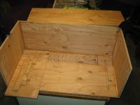
Larval Karlflex
It doesn't yet look like much ... The innards and baffle will go in tomorrow ..
Im starting to feel more confident with this tablesaw 🙂
It doesn't yet look like much ... The innards and baffle will go in tomorrow ..
Im starting to feel more confident with this tablesaw 🙂
Attachments
Last edited:
XRK,
Ok , i am trying out cusp versus slot style apertures and it does change things a bit .... Pipe harmonics still seem to create some interference with bumps & dips in the midrange response but i am curious to see how similar the real world measurements look ... Do you notice some midrange discrepancy between your simulated K-boxes and their measured response?
I will read through the Karlson thread in order to try to better understand what you are describing here ..... I have managed to link the dimensions of the K-ap ports to the radiators using the "DEF=" command which speeds up the process of adjusting the aperture contours and areas, but i have a way to go before tying everything into a master equation ...
But hey , XRK, I did figure out something intriguing yesterday that might be of interest to you since you build K-subs with smaller drivers .... I am able to get (according to sim) the same output and excursion control from a simplified (more helmholtz based) tri-chamber Karlflex type cab (Like a DCR-Kcab hybrid) compared to a Tri-chamber Karlflex with long path (eigenmode version) ....... Not sure if i believe it since i have always had better luck getting satisfying low-end with quarter wave loaded cabs, but this is so simple and easy to scale down for small drivers that it is very tempting.
The parasitic chamber is well damped (using stuffing) on this cabinet tuned to between 1.6 and 1.9x fundamental and it reduces excursion by 2mm on the PA-310 which allows 38v input (instead of 28v) while still staying within the safe physical range for that driver ... Along with the extra 30 liters of cabinet size gives me an additional 4db output according to Akabak! 😀 This is a great thing for a driver that has so much thermal power handling yet so little physical capability ..... Might be something that could be useful for an XKi type box with drivers that like this Dayton have plenty of electrical power handling yet low xmax 🙂
Both sims here are using the "cusp" style K-aperture ...
That is interesting that the parasitic chamber is connected to its own vent? What does that do?
Btw, you can scale your plot box vertically and it will increase resolution to 5dB per div. Then go to the edit menu and copy as bitmap. Then paste into paint or whatever program and save a png file. Your plots will look better and not have the windows dialog box around it.
Admiral Akbar warns us by saying: "ITS A RANT!"
Yessir! The parasitic chamber has it's own vent ..... The idea is just a stretched out twist on the old "DCR" (Dual Chamber Reflex or Double Chamber Reflex) concept developed countless ages ago by some sharp fellow named G Augspurger (and updated by Weems at some point from what i have read *shrug*) 😀 I am sure you know about the DCR concept already .... I have always been fascinated with the idea of being able to place a second strong resonance (above the fundamental) near or just above the peak in excursion which will also be in the same vicinity as the peak in impedance (the "anti-resonance" region? I have heard some people call it that but i am not sure if that is a proper term for it) ..................Anyway, of course the idea is to place this extra resonance very near what would normally be the so called "anti-resonant"(?) range improving control over the cone and improving power delivery, basically improved loading in general where it is needed most! ........ The small chamber & vents accomplish this in a parasitic manner meaning it draws energy away from the rest of the system (effectively damping the driver and the larger chamber) when the parasitic section becomes active (in this case around 75hz with the tri-chamber Karlflex), meanwhile at lower frequencies near the box fundamental (40hz in this case) that same extra chamber&vent set simply behave like an additional port plus a little more box volume acting basically like a split path (NOTE: this secondary port/radiator eases main port velocity near fundamental which is definitely a perk! BLESSED BONUS BATMAN!
  )
)
So enough of the basic theory on DCRs (aka "ABC box" in some circles)
Going beyond the typical textbook implementation is where things get a little more interesting:
Every Augspurger-Weems example i have seen operate as helmholtz based boxes using chambers & ports ....... I wanted to try to adapt this DCR concept to quarter wave or eigenmode resonant cabinets so i simply stretched out the aspect ratio and tried to figure out where a logical place to tap-in to the main path would be ....
A great place (as far as i can tell) to tap-in to the main path with our interchamber port would be near the driver in an offset-driver pipe system like the Karlflex ...
Almost exactly one year ago (in may of 2014) I designed a set of OD-MTM-TL towers with the DCR feature for a local friend to be used as the mains in his home theater system, he built them, and they work surprisingly well for having only two 5.25" drivers in each tower ... I verified impedance with the DATS and they certainly had the distinct DCR impedance signature ...... They also produced excellent bottom end with an almost eery lack of cone movement, a success for certain! , but of course they were not tuned nearly as low as these PA-310 cabs will be tuned and my friend's towers were TLs (QWPs) (4th order) not 6th order like the Karlflex so this experiment is a little bit different...
So, ok, back to the present, it is pretty easy to simulate a DCR styled parasitic chamber in Akabak using a small "DUCT" tapped into the main path .... This "interchamber" duct then proceeds to a larger "DUCT" with significantly more CSA then connects to a smaller duct-->radiator ..... I figured out (in sim) that there is a relationship between parasitic resonance Q and the ratio of the large duct (in middle) to the small ducts (at each end of large duct) , this could possibly be useful! In this Karlflex with DCR feature i used a 3:1 ratio , meaning the large duct has 3x more CSA than the interchamber and exit ducts .... Going to a 4:1 ratio or higher would raise the Q and likely increase the dip in response near the parasitic resonance frequency ........ The lower ratio requires only a small amount of lining/stuffing ("VISC=20"-ish or less in the larger parasitic duct) in order to accomplish the following two things: 1 minimize the dip in response that occurs around the parasitic resonance and 2. spreads the parasitic resonance out a little bit to more effectively control the excursion peak ......I can verify all of this in simulation but needless to say all of these Akabak observations are virtual, i will be very happy if things pan out well in reality over the next few days as i test this new box
ANOTHER NOTABLE AKABAKISM: For some reason the large duct section belonging to the parasitic chamber system in this Karlflex cannot be replaced with a similarly sized waveguide without running into issues revolving around ineffective damping ........ Yet on the contrary i have also found that a waveguide using acouresistance is far superior for simulating the S1 section in the Karlflex mainly because of the way pipe harmonics are handled........
It seems that a waveguide's "acouresistance" function can be very different than a duct's "VISC=" function depending on the situation, Not really sure what to make of the extreme discrepancies in damping functions but i suspect it may revolve around the size or proportions of the component (duct or waveguide)...
Ok , sure thing, I will post a new plot here soon using that method 🙂
That is interesting that the parasitic chamber is connected to its own vent? What does that do?
Yessir! The parasitic chamber has it's own vent ..... The idea is just a stretched out twist on the old "DCR" (Dual Chamber Reflex or Double Chamber Reflex) concept developed countless ages ago by some sharp fellow named G Augspurger (and updated by Weems at some point from what i have read *shrug*) 😀 I am sure you know about the DCR concept already .... I have always been fascinated with the idea of being able to place a second strong resonance (above the fundamental) near or just above the peak in excursion which will also be in the same vicinity as the peak in impedance (the "anti-resonance" region? I have heard some people call it that but i am not sure if that is a proper term for it) ..................Anyway, of course the idea is to place this extra resonance very near what would normally be the so called "anti-resonant"(?) range improving control over the cone and improving power delivery, basically improved loading in general where it is needed most!
........ The small chamber & vents accomplish this in a parasitic manner meaning it draws energy away from the rest of the system (effectively damping the driver and the larger chamber) when the parasitic section becomes active (in this case around 75hz with the tri-chamber Karlflex), meanwhile at lower frequencies near the box fundamental (40hz in this case) that same extra chamber&vent set simply behave like an additional port plus a little more box volume acting basically like a split path (NOTE: this secondary port/radiator eases main port velocity near fundamental which is definitely a perk! BLESSED BONUS BATMAN! ) So enough of the basic theory on DCRs (aka "ABC box" in some circles)
Going beyond the typical textbook implementation is where things get a little more interesting:
Every Augspurger-Weems example i have seen operate as helmholtz based boxes using chambers & ports ....... I wanted to try to adapt this DCR concept to quarter wave or eigenmode resonant cabinets so i simply stretched out the aspect ratio and tried to figure out where a logical place to tap-in to the main path would be ....
A great place (as far as i can tell) to tap-in to the main path with our interchamber port would be near the driver in an offset-driver pipe system like the Karlflex ...
Almost exactly one year ago (in may of 2014) I designed a set of OD-MTM-TL towers with the DCR feature for a local friend to be used as the mains in his home theater system, he built them, and they work surprisingly well for having only two 5.25" drivers in each tower ... I verified impedance with the DATS and they certainly had the distinct DCR impedance signature ...... They also produced excellent bottom end with an almost eery lack of cone movement, a success for certain! , but of course they were not tuned nearly as low as these PA-310 cabs will be tuned and my friend's towers were TLs (QWPs) (4th order) not 6th order like the Karlflex so this experiment is a little bit different...
So, ok, back to the present, it is pretty easy to simulate a DCR styled parasitic chamber in Akabak using a small "DUCT" tapped into the main path .... This "interchamber" duct then proceeds to a larger "DUCT" with significantly more CSA then connects to a smaller duct-->radiator ..... I figured out (in sim) that there is a relationship between parasitic resonance Q and the ratio of the large duct (in middle) to the small ducts (at each end of large duct) , this could possibly be useful! In this Karlflex with DCR feature i used a 3:1 ratio , meaning the large duct has 3x more CSA than the interchamber and exit ducts .... Going to a 4:1 ratio or higher would raise the Q and likely increase the dip in response near the parasitic resonance frequency ........ The lower ratio requires only a small amount of lining/stuffing ("VISC=20"-ish or less in the larger parasitic duct) in order to accomplish the following two things: 1 minimize the dip in response that occurs around the parasitic resonance and 2. spreads the parasitic resonance out a little bit to more effectively control the excursion peak ......I can verify all of this in simulation but needless to say all of these Akabak observations are virtual, i will be very happy if things pan out well in reality over the next few days as i test this new box
ANOTHER NOTABLE AKABAKISM: For some reason the large duct section belonging to the parasitic chamber system in this Karlflex cannot be replaced with a similarly sized waveguide without running into issues revolving around ineffective damping ........ Yet on the contrary i have also found that a waveguide using acouresistance is far superior for simulating the S1 section in the Karlflex mainly because of the way pipe harmonics are handled........
It seems that a waveguide's "acouresistance" function can be very different than a duct's "VISC=" function depending on the situation, Not really sure what to make of the extreme discrepancies in damping functions but i suspect it may revolve around the size or proportions of the component (duct or waveguide)...
Btw, you can scale your plot box vertically and it will increase resolution to 5dB per div. Then go to the edit menu and copy as bitmap. Then paste into paint or whatever program and save a png file. Your plots will look better and not have the windows dialog box around it.
Ok , sure thing, I will post a new plot here soon using that method 🙂
Last edited:
Great curves
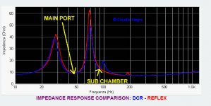
Here is what i meant (in the rant above) about the distinct DCR impedance curves ....
One is Claudio Negro's comparison of a DCR Reflex (blue) versus standard Reflex (in red) where he shows the DCR's upper impedance peak being slightly suppressed with a notch being taken out of the upper slope ...
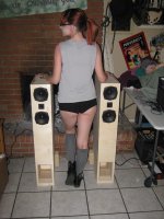
The second photo is a screenshot of the impedance graph produced by my DATS unit connected to our homebrew DC-OD-MTM-TL towers that we crafted for my friend's home theater system about a year ago ... You can see the resemblance except the notch in the upper peak is more prominent to such an extent that it basically splits the big peak into two almost equal peaks .....😀
So if i can do this with an offset-driver TL (QWP) , then why not a Karlflex or a Tapped Pipe or even a Tapped Horn if i wanted? ..... It complicates the design but when you are using a driver that severely lacks excursion (in relation to it's thermal power handling) then it may be worth the extra effort🙂
Hopefully the impedance curve of this Pa-310 Karflex will look similar to either of these other dual chamber examples so i know that i landed the parasitic resonance in the right range ..
The third picture shows the special DC-style MTM-TL towers, thanks to our comely friend Annabelle for modeling with them
Here is what i meant (in the rant above) about the distinct DCR impedance curves ....
One is Claudio Negro's comparison of a DCR Reflex (blue) versus standard Reflex (in red) where he shows the DCR's upper impedance peak being slightly suppressed with a notch being taken out of the upper slope ...
The second photo is a screenshot of the impedance graph produced by my DATS unit connected to our homebrew DC-OD-MTM-TL towers that we crafted for my friend's home theater system about a year ago ... You can see the resemblance except the notch in the upper peak is more prominent to such an extent that it basically splits the big peak into two almost equal peaks .....😀
So if i can do this with an offset-driver TL (QWP) , then why not a Karlflex or a Tapped Pipe or even a Tapped Horn if i wanted? ..... It complicates the design but when you are using a driver that severely lacks excursion (in relation to it's thermal power handling) then it may be worth the extra effort🙂
Hopefully the impedance curve of this Pa-310 Karflex will look similar to either of these other dual chamber examples so i know that i landed the parasitic resonance in the right range
..The third picture shows the special DC-style MTM-TL towers, thanks to our comely friend Annabelle for modeling with them
Attachments
Last edited:
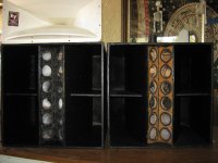
progress
Almost there🙂 (check out the attached photo)
Almost there🙂 (check out the attached photo)
Attachments

Last edited:
Almost there🙂 (check out the attached photo)
Nice work, the understanding you have on ports and resonances as applied to these designs is impressive, thinking outside the norm, not being a follower leads you to explore things only a few have an understanding of, rather than trying to copy the latest trend. It is great that you are now able to build and test your hypothesis. I wish I had the time you have to enjoy such persuits.
I do notice in the pic that the joints are less than perfect, this is where PL glue works wonders with such a complex box. It would be a shame if leaks hindered the performance.
I still intend on building your design for the 10s you gave me. Shed is almost done, just where to find the time.
 Mr Pete !! Good to hear from you! 🙂
Nice work, the understanding you have on ports and resonances as applied to these designs is impressive, thinking outside the norm, not being a follower leads you to explore things only a few have an understanding of, rather than trying to copy the latest trend. It is great that you are now able to build and test your hypothesis.
Thank you Sir! I have been working on developing a better understanding and a "feel" for how it all works with the intention of making something different, something refreshing, because i was just so tired of seeing everyone regurgitating the same alignments over and over and over again, tapped horns , front loaded horns , sealed boxes , reflex boxes blah blah blah , i wanted something different, or at least an interesting modification to the tired old designs ...
I am very happy to have some of the proper woodworking tools now so i can build things without having to rely so much on folks like my buddy Tim or others to use their woodshop, it was just too inconvenient having to work around their schedules and projects ended up being delayed and drug out for far too long, progress was too slow ............ Now i can hang out on my patio in my bunny slippers and my bathrobe zipping out panels with the tablesaw and gluing acoustic contraptions together while sipping lemonade that my girlfriend just made and hanging out with my cats 😛 LIFE IS GOOD! 😀
I do notice in the pic that the joints are less than perfect, this is where PL glue works wonders with such a complex box. It would be a shame if leaks hindered the performance.
You have a good eye Pete! Yes, you are right, my cuts aren't all very precise yet ..... I bought a couple of tubes of the PL ("premium 3x" it says on the tube) in order to put the side panel on so everything seals well, but before i do that I have some weather stripping on the edges of the panels for experimentation with stuffing & such before i use the PL to permanently attach the side ...
I will post some measurements & pictures here in a bit ........... I think i might have a leak in my application of weatherstrip or a phase issue or something so i am trying to sort that out before moving forward ....
I still intend on building your design for the 10s you gave me. Shed is almost done, just where to find the time.
Cool man, good timing on the shed, the brutal heat will arrive all too soon ...... Those boxes for the 10s should be fun, quick and straightforward

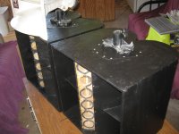
I patched up your old DR250s , fixed the damage, and Adam and I just finished painting them with black Duratex on tuesday , they are looking pretty sharp! ... I even got new neutrik speakon connectors for them and new cabinet corners (still have to put on the corners) ... Also still have to seal the front columns (where the piezo tweets used to go)..... I will attach a few pictures for you to see ...
We also found out that pairing up those big white EV HR60 horns with your DR250s seems to be a winning combination ..... I screwed on a few of my Selenium d220ti compression drivers to the back of the EV horns and used a super simple crossover (one that compensates for the "CD horn" tilt in response) which gave us support down to around 1k ( precisely what the 250s really needed with those P-audio drivers) ... Good match, sounds nice ..... I guess these will go together as a set now, so i am going to build small boxes to enclose the HR60s , and they should fit nicely on top of the 250s because they are the same width
 ..............
The Facebook sound group misses you, I have been doing my best to keep it somewhat active while you are on vacation 🙂
Attachments

Last edited:
- Home
- Loudspeakers
- Subwoofers
- New sub design? Constricted Transflex, simple build (series tuned 6th order)