Saba & BeauB ,
Sure, no prob i will draw up a sketch or two maybe a plain ole TP and then an ML-TP if it looks good in sim with that Eminence driver ... I imagine the ML-TP would be a better way to go though since the magnet will stick out of the traditional TP a bit much ..
Saba, you are right, the driver's FS can be well above FB, sometimes as much as 1.6x fb (think "golden ratio" as the upper limit of what is ideal)... A driver with an fs of 60hz can work great in a 40hz tapped pipe if the other specs are in the right ranges.
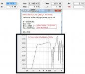
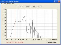
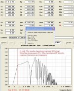
For example: punch these following figures (attached) for this hypothetical 55hz fs driver into hornresponse and sim this driver in the exact same 144 liter 35hz tapped pipe that was created for the Eminence .... Notice how the response now has a lovely slight upward tilt now with no saddle, and the extension is now almost usable to 30hz!
Take a look at the attached screenshots. Same power input, same box, the only difference is a hypothetical custom driver ..... As i was finishing this i realized that i made the QMS a little unreasonably high, so i made a note of it on the screenshot .... Its really too bad that we don't find more drivers with specs like these to work with , some OEMs will make customs like this though, in fact i think Eminence offers that service , not sure what the minimum order would have to be though ..
Sure, no prob i will draw up a sketch or two maybe a plain ole TP and then an ML-TP if it looks good in sim with that Eminence driver ... I imagine the ML-TP would be a better way to go though since the magnet will stick out of the traditional TP a bit much ..
Saba, you are right, the driver's FS can be well above FB, sometimes as much as 1.6x fb (think "golden ratio" as the upper limit of what is ideal)... A driver with an fs of 60hz can work great in a 40hz tapped pipe if the other specs are in the right ranges.
For example: punch these following figures (attached) for this hypothetical 55hz fs driver into hornresponse and sim this driver in the exact same 144 liter 35hz tapped pipe that was created for the Eminence .... Notice how the response now has a lovely slight upward tilt now with no saddle, and the extension is now almost usable to 30hz!
Take a look at the attached screenshots. Same power input, same box, the only difference is a hypothetical custom driver ..... As i was finishing this i realized that i made the QMS a little unreasonably high, so i made a note of it on the screenshot .... Its really too bad that we don't find more drivers with specs like these to work with , some OEMs will make customs like this though, in fact i think Eminence offers that service , not sure what the minimum order would have to be though ..
Attachments
XRK ,
This old beta version of WinISD (v .60a1) will do DCRs but in this software they call them "ABC" like the car audio guys often refer to them as (even though the term DCR is more appropriate) ...
I just tried to upload the file but it is bigger than DIYaudio will allow, it is 1.6 megs ...
This link should work temporarily: http://www.filedropper.com/winisd06020071207
I definitely need to start learning Akabak, i will have to start looking into those tutorials.
Last edited:
Saba & BeauB,
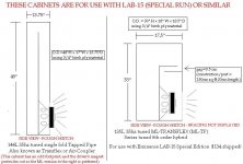
Here is the 2D side view sketch you guys were asking for 🙂
The ML version cabinet looks pretty good ... I will attach the HR inputs and halfspace response for it as well... Had fun experimenting with moving the constriction up and down the path a little bit to contour the response ... Moving the constriction upwards (away from the magnet side of the driver just by a few inches) filled in the saddle to some extent at the expense of a small amount of bandwidth, i found that i was able to shave off a few liters from the cabinet size as well ..... This adjustment could probably be also used to further refine the SWE-10S4 ML-TP boxes ... You just leave the chamber area,port and segment sq cm areas all the same while decreasing VTC and increasing L23 to shift the constriction up the line while bringing the FB back to 35hz as you go ... Reverse the process in order to move the constriction down the line (closer to the driver)..
The ML-TL has more bandwidth (compared to the tapped pipe) , a nice square-ish footprint and the magnet wont stick out of the hybrid like it does with the single fold TP ..
Attachments
Last edited:
Saba & BeauB,
Here is the 2D side view sketch you guys were asking for 🙂
The ML version cabinet looks pretty good ... I will attach the HR inputs and halfspace response for it as well... Had fun experimenting with moving the constriction up and down the path a little bit to contour the response ... Moving the constriction upwards (away from the magnet side of the driver just by a few inches) filled in the saddle to some extent at the expense of a small amount of bandwidth, i found that i was able to shave off a few liters from the cabinet size as well ..... This adjustment could probably be also used to further refine the SWE-10S4 ML-TP boxes ... You just leave the chamber area,port and segment sq cm areas all the same while decreasing VTC and increasing L23 to shift the constriction up the line while bringing the FB back to 35hz as you go ... Reverse the process in order to move the constriction down the line (closer to the driver)..
The ML-TL has more bandwidth (compared to the tapped pipe) , a nice square-ish footprint and the magnet wont stick out of the hybrid like it does with the single fold TP ..
Thank you so very much. This certainly fits the foot print I have available. There may be a couple of additional dimensions I need, but let me see if I can figure those out first.
Again, thanks.
Last edited:
 Correction to the typo above: I meant to to say "The ML-TRANSFLEX (ML-TP) has more bandwidth (compared to the tapped pipe)" but you guys get the gist of it 😛
........
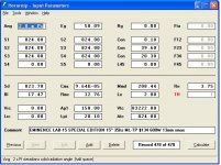
 Also, another correction, here (attached) is a more realistic set of parameters for our hypothetical driver with higher FS for use in a 144L 35hz tapped pipe ... FB:FS ratio (35hz:55hz) is loosely based on 1:1.6 Golden Ratio ..... It is a fun and useful exercise to simulate an ideal driver like this in order to compare it's performance to the real-world driver that you will actually use, so you can get a feel for how appropriate your choice in drivers is for a particular cabinet design... In other words: If you aren't disgusted by the discrepancy in performance then just go with it !

At this high FB:FS ratio it seems that an unusually tight VAS figure (but not impossibly tight) is called for, high motor strength, light cone (fine for this low compression cabinet), low inductance, high QMS figure .....
In a less extreme scenario (if the driver has a somewhat lower FS rating, but still well above FB) like an FS in the range of 45hz or 50hz then the suspension can be more relaxed (higher VAS figure) and LE can also fall into more typical ranges ..
All of these parameters can be adjusted and experimented with by using the "DRIVER" option (in the center drop down menu) within Hornresponse's wonderful "Loudspeaker Wizard" feature.
THANK YOU DAVID McBEAN! YOU ARE A GREAT MAN FOR MAKING HORNRESPONSE AVAILABLE TO THE WORLD! <3
Attachments
Last edited:
Thank you so very much. This certainly fits the foot print I have available. There may be a couple of additional dimensions I need, but let me see if I can figure those out first.
Again, thanks.
FANTASTIC!!! I am glad the footprint works for you BeauB ... The standard single fold tapped pipe had too many issues with trying to fit this large driver into such small pipe, so i knew i had to conjure up an alternative with a larger footprint.
Feel free to ask about dimensions if you need ..... I may post a more detailed sketch of that 135L ML-Transflex here soon when i have a chance ...
Last edited:

FANTASTIC!!! I am glad the footprint works for you BeauB ... The standard single fold tapped pipe had too many issues with trying to fit this large driver into such small pipe, so i knew i had to conjure up an alternative with a larger footprint.
Feel free to ask about dimensions if you need ..... I may post a more detailed sketch of that 135L ML-Transflex here soon when i have a chance ...
Well, here are my questions:
What is the spacing of the straight portion of the (L-shaped) middle divider? Can I assume that should be centered on the mid-point of the depth of the box (i.e., the middle of 17.5” (8.75”)?
As to the shorter (L-shape) part of the middle divider, what is the length of that, and how far should it end from the internal wall ?
As to the shorter port wall (the straight one that parallels the shorter (L-shape) part of the middle divider) what is its length, and how far from the middle divider wall should it end? At what length from the end of the box should this port wall be spaced?
What is the distance between the shorter (L-shape) part of the middle divider and the shorter port wall?
How long is the terminus (i.e., from the end of the box – what is the size of the opening)?
Sorry - my being so uninformed is a drag. The answers may be obvious to others.
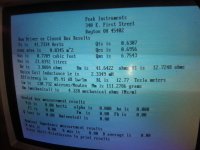
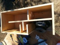
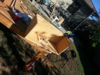
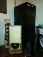
ON another note, putting on last panel of (10 inch woofer ML-TP SWE10s4) my build today. Who's excited? First notes tomorrow assuming things go well (and with crap tons of PL things usually go well 🙂)
Here are some pics to go along with the build.
Yes that is a DOS version of PE woofer tester from forever ago (not my computer, a custom audio amplifier designer let me use it.)
Here are some pics to go along with the build.
Yes that is a DOS version of PE woofer tester from forever ago (not my computer, a custom audio amplifier designer let me use it.)
Attachments
Last edited:
Saba,
LOOKING GOOD!
So exciting!
I am fully enthused to hear your impressions of it🙂
It might be worth putting that box back into simulation so i can try to fine tune it a little bit by shifting the constriction up or down the path by a few inches like i did with the Eminence based ML-TP ... I was able to optimize things even further that way, it could mean another revision of the SWE-10S4 ML-TP box..
Last edited:
BeauB ,
You are correct , the vertical divider/baffle panel is to be centered in regards to depth ... The distance you end up with between the center divider and the inside of the rear (or front) panel will also be the same as the distance between the upper face of the L-shape panel and the bottom face of the top panel ......
I prefer a lot of repeating measurements throughout my designs (if possible) for the sake of elegant simplicity, or maybe it is just easier for me to "wrap my head" around the design that way
The same goes with the formation of the constriction/port section .... The 3.5cm measurement repeats throughout that structure .....
The terminus/mouth can match the sq cm area of the path (824 cm sq in this case) but increasing or decreasing that area can be an effective and convenient way to fine tune the FB of your box ... For example if the fundamental resonance measures a little high then you can reduce the terminus area to provide some additional mass loading which will tune it lower just slightly , and the reverse is also true meaning if you want the box tuning to increase a little you can open up the area a bit.
Last edited:
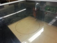
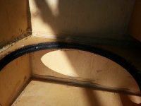
PS that's what happens when you laser cut a baffle hole 🙂 char city. structurally fine but the outer layer looks like a burnt forest.
Saba,
So exciting!
I am looking forward your impressions of it🙂
You'll be the first to know after my house mates 🙂.
ON another note, putting on last panel of (10 inch woofer ML-TP SWE10s4) my build today. Who's excited? First notes tomorrow assuming things go well (and with crap tons of PL things usually go well 🙂)
Here are some pics to go along with the build.
Yes that is a DOS version of PE woofer tester from forever ago (not my computer, a custom audio amplifier designer let me use it.)
Name the car and the Makita tool and you win brownie points.
Just realized that the Makita is a giveaway if you look closely, still guess away 😛
That lasered black charring is quite dramatic! Like eyeliner around the eye of a giant gothic cyclops! Sounds like something from an episode of SouthPark ... A giant goth subwoofer cyclops stomping around in oversized platform boots and destroying buildings by playing music like The Cure and Joy Division at excessive levels in revolt against conformity!🙄
Last edited:
BeauB ,
You are correct , the vertical divider/baffle panel is to be centered in regards to depth ... The distance you end up with between the center divider and the inside of the rear (or front) panel will also be the same as the distance between the upper face of the L-shape panel and the bottom face of the top panel ......
I prefer a lot of repeating measurements throughout my designs (if possible) for the sake of elegant simplicity, or maybe it is just easier for me to "wrap my head" around the design that way
The same goes with the formation of the constriction/port section .... The 3.5cm measurement repeats throughout that structure .....
The terminus/mouth can match the sq cm area of the path (824 cm sq in this case) but increasing or decreasing that area can be an effective and convenient way to fine tune the FB of your box ... For example if the fundamental resonance measures a little high then you can reduce the terminus area to provide some additional mass loading which will tune it lower just slightly , and the reverse is also true meaning if you want the box tuning to increase a little you can open up the area a bit.
Thanks again - I'll draw it with dimensions - and then plan the build.
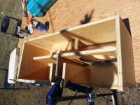
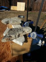
Guys, it's all done. Letting it cure before power on, I need advice on how to seal the driver in the chamber, It doesn't exactly have a rear mount gasket (tiny amount of rubber seal surrounded by the metal surround). Can I just crank it down with the T-nuts until the metal seals on the wood? Right now it is "loosely tightened" for the sake of the comparison to the "big mama" (T60 by BFM) that I wanted to include for size comparison.
Why rocks you ask? Because I'm all for overkill on the final panel and I never have enough clamps -- especially ones that can put force on the middle, double the PL I usually use + whatever "weight" I can find (this time it was rocks).
I would rather not flip the driver around because I don't have a speaker terminal hole yet and would like to just wire to the speaker terminals on the driver (eventually I expect to flip the driver around (cone facing towards outside) with wiring going to speakons on the opposite side and some decent slack line for maintenance purposes.
Attachments
PS. I do have some weather stripping I typically use for sealing driver chambers, would this be a solution? Meaning wrap a circle with the tape, I think it's 1/2 inch wide, and poke holes for the bolts?
Yeah, the weather stripping could work .. Or perhaps cut a big ring gasket out of something like rubber or foam or cork ...
Its great that you are using PL in your build ... Love that stuff ... Regular wood glue just runs too easily and cannot guarantee that your internal panels seal correctly, but using a thick construction adhesive like PL solves that problem 🙂
I also like your use of stones 😉 ..... You are a stoner , Its official 😛
You could absolutely reverse the driver if you like as you mentioned, although the magnet out mounting provides nice cooling ... The only difference you might hear (or measure) by flipping the driver the other way is a very small upward shift in FB, and probably a decrease in the small chamber's midbass resonant frequency since it would now have a little more airspace to work with.....
Last edited:
- Home
- Loudspeakers
- Subwoofers
- New sub design? Constricted Transflex, simple build (series tuned 6th order)