I am looking at Saba's high/low power graph right now ... The relative bump (or lack of loss?) centered close to 50hz is interesting .... Also , did you guys notice that around 80hz he is only getting a difference of about 10db versus 15-ish db near and just above FB (along with many other areas) ... ? That seems odd ..
According to simulations the port velocity is greatest in the vicinity of FB correct? So it seems that these results are sort of counter-intuitive since he seems to have less loss at around FB when compared to 80hz... hmm .. Should be the reverse if the loss is based upon excess velocity ... What do you suppose that is all about? Anyone?
More likely than not this is a room issue, significant null above 75 hz or so. The measurement was not expected to be useful up high but rather down low. Anyways unless someone wants to buy me a replacement SPL meter I'm done measuring response.
I have to ask what is the point of the constriction? Is it just for the sake of doing a new and different design concept? Besides the novelty aspect it doesn't really seem to outperform other alignments that are easier sim, easier to lay out and easier to build and have no constrictions.
For example here's a simple reverse taper offset tl. It's not a particularly good tl but I tried to follow the response shape as closely as possible to the design I was emulating, the one in post 260 and I'm not sure which features are desired. I think someone mentioned that the bump down near tuning and was cool as well as a bit of a saddle. (The low knee bump in mine is a bit higher in frequency but it could be lowered with a bit of redesign or a bit of eq.) I also kept the spike up higher, slightly out of a sub's normal bandwidth. Not sure why you would want that but it's there. I think mine is 5 liters larger. I used CON segments because the design in post 260 did, which isn't right but it makes for a fair comparison.
I showed both at the same power input (the constricted design is in light grey) and the simple tl outperforms the constricted design at all frequencies between about 38 and 140 hz and it does it with less excursion. Mine is tuned a couple hz higher though, so all in all they are about even, louder/lower cancels out. This is a 5 minute sim and it could definitely be improved, so you can see you don't need a constriction for any reason that I can see. AFAIK Brian used the dogfood constriction because it fixed something he didn't like in an existing design, I'm not sure it's the best idea to use it as an exclusive design feature for a new design.
I also included the graph for vent velocity for my simple tl. Flare It says my port is plenty large enough, by the Flare It standard I could reduce it quite a bit but I prefer not to, in fact I would prefer it to be larger but there's only so much you can do with the goals I was trying to achieve here - mainly to emulate the design in post 260 as closely as possible with a simpler design.
Anyway, I realize I've nitpicked everything here to death and I do apologize for that because I really do appreciate the innovation and enthusiasm going on here but I can't see any good reason to use a constriction if you don't have to and I just wanted to let you know IMO it's not a good idea.
An externally hosted image should be here but it was not working when we last tested it.
What would this look like? Can you give us a side sketch so we know what we would be looking at?
I appreciate the criticism, honestly I'm just looking for the best compact design choice. If your TL design sims better I'm all for it! (referring to just a guy)
I appreciate the criticism, honestly I'm just looking for the best compact design choice. If your TL design sims better I'm all for it! (referring to just a guy)
It doesn't sim better, I tried to make it as similar as possible to the alignment I was comparing to (but without a constriction) to make the point that a constriction is not needed. Aside from the compression issue there really isn't much difference, that's the point. There's no free lunch, any alignment that can be used to get somewhat flat response out of the intended bandwidth in the same size package will sim approximately the same, especially in the low end.
It's a simple single fold tl, but it would have to be changed to PAR segments and ideally it should be refined (or completely redesigned), it's really not (and wasn't intended to be) an ideal design.
Last edited:
I have to ask what is the point of the constriction? Is it just for the sake of doing a new and different design concept?
It all started when i was trying out different alignments with the Alpine 10s , this seemed to be something that worked well for them .... The LAB 15 (special) was just a curiosity that I fiddled with just recently when i noticed that it was a good value ... At first when trying it out in a standard non-tapered tapped pipe tuned to 35hz i realized that the driver was an overly tight fit and i wondered if it would work better in a scaled up version of one of my ML-Transflex designs which would have a more accommodating footprint ..... So that was the progression ...
For myself there is certainly an attraction in wanting to try something new and different, and i think that is because when browsing the forums or visiting websites to look at various high performance designs all i see is the same things rehashed and regurgitated over and over and over ad infinitum ....
I think some innovation or new ideas would be good, not that THIS is an extraordinarily innovative idea necessarily because i know that this ML-Transflex is just a remix of some age old concepts, but it is arranged to be fun and quick/simple to build, small, and happens to work great with some low cost drivers ... Having something unique also has a certain appeal to people, and even better if it performs well .. BONUS!🙂
This discussion has also been a great exercise, a learning process and a way to explore some new possibilities.. The exchange has been thought inspiring and positive in general... I enjoy the debate and sharing of ideas ...
JustaGuy , your reverse taper TL looks like it would work well for the special Lab 15 , should have a large enough footprint to fit the driver , and is certainly simple enough.... I think you are right that the difference in SPL and excursion is probably somewhat due to the slightly higher tuning... That driver just seems to model exceptionally well in a TL...It also looks good in a reverse taper tapped pipe having a little more of a bump at FB + a saddle at this VB but adding a little stuffing in the first 3rd of the path would fix that right up 🙂 .. The Alpines look good in a TL as well ....
I have conducted a few recent real-life experiments with some unique DIY parasitic resonator enhanced boxes and their measurements look very promising but i need to do some more work to make sure i understand what is going on inside of these cabinets before i can even begin to discuss them on a busy forum like this, i want to make sure i know what i am talking about before initiating any discussion about something unorthodox 🙂... If all goes well i should hopefully have something really special to offer up to this community in the future..
Last edited:
All this hand waving was over compression, not chuffing, I think I mentioned that about a dozen times. Port compression is distortion. If you think there's enough compression near the end of the line in the low pressure high velocity end of the box to destroy the driver I can't see how this isn't an issue.
I'm not familiar with Olson's stepped blh but if it's like all other stepped blhs, the small ducts are in the throat, the low velocity part of the horn, and he probably used very low xmax drivers so this isn't anything close to the initial expansion in an antique blh.
I don't have time to read everything in fast moving technical threads such as this one, especially ones where I don't agree with much of what's being posted, just saw the word used repeatedly.
Again, I don't consider it an issue unless it's a sustained high power app where the driver's construction may not be designed for it.
He did, but it's irrelevant! I used the math that's been proven over decades of high sustained power prosound horn apps to get the averaged throat area over distance for a stepped pipe version of a 0.736 M [T] hypex, so confidant that if there's any compression from high power transients in a HIFI/HT app it will be more due to thermal power compression than any pipe segment constriction.
GM
slightly OT but post 260 could provide a reflector for a K-type
So true, it is starting to resemble a Karlson ... Hey now, Come to think of it, doesn't the "Karlsonator" even have a constriction in the path that vents into the front chamber followed by a little more path and ..... Well damn ... thats pretty familiar ....
Was there ever any complaints about the Karlsonators having any port compression due to the constriction?
Yeah, it’s not a vent, it’s just a stepped open pipe segment connecting a larger closed pipe and reflex compression chamber, so its air mass ‘slug’ is trapped between two mismatching acoustical impedance junctions. In this context we can view it from the reflex side as the initial expansion in a BLH, ergo all we need to do in theory is taper it slightly, but in reality it’s well proven that using relatively short lengths of straight pipes laid out in multiple bends like Olson did with his BLH only rolls off unwanted HF content.
All this ‘hand waving’ over ‘chuffing’, high vent velocity = distortion seems irrelevant to me as it’s going to be damped by the two segments it connects to.
FWIW, using Prof. Leach’s math, I get a ~76.52 cm^2/11.86”^2 ‘vent’ pipe, so had I done your alignment this is what I would have used.
If sustained high power apps compression is the primary concern, then increase its area/length to lower its compression ratio lest it maybe damage the driver; otherwise, ‘much ado about nothing’ to my way of thinking.
GM
I just remembered I actually started a thread asking about the max allowable velocity in a horn throat a few years ago, maybe weltersys remembers this too. There was a guy that seemed like he knew what he was talking about, he said for Art's Keystone throat size with a very smooth pvc surface, 30 m/s would start to detune it and by 38 m/s it would be completely turbulent. When I asked how to calculate acceptable velocity for smaller throats he said
Do you have Flair-it? Flare-it - Free Speaker Design Software This will give you Basic guidelines for how fast air can move in small spaces.
But remember, this gives values for very smooth surfaces in a circular port. A square port has ~13% more surface area.
He had previously mentioned that he independently verified that Flare It is very accurate.
Also note that he is talking about smooth (not stepped) expansion, stepped would be far worse.
I don't have the math skills to back up his statements but if he's right, this is a lot more useful than Olson's blh example with (probably) almost zero excursion driver. I'm pretty sure the last thing on Olson's mind was throat turbulence and/or distortion caused by small ducts, if he ever measured it or even mentioned it I'd like a link. In fact I'd like ANY links that show " relatively short lengths of straight pipes laid out in multiple bends like Olson did with his BLH only rolls off unwanted HF content." While this is almost certainly true for old blhs with fractional mm xmax fullrange drivers and reasonably sized ducts, I'm not buying it for modern high excursion sub drivers and unreasonably small ducts. The software backs me up.
The thread is probably worth a read, even if you only read revboden's posts, there are not many. http://www.diyaudio.com/forums/subw...-compression-ratio-different-perspective.html
He says basically exactly what I've been saying but in a more technical manner.
I don't have time to read everything in fast moving technical threads such as this one, especially ones where I don't agree with much of what's being posted, just saw the word used repeatedly.
Again, I don't consider it an issue unless it's a sustained high power app where the driver's construction may not be designed for it.
He did, but it's irrelevant! I used the math that's been proven over decades of high sustained power prosound horn apps to get the averaged throat area over distance for a stepped pipe version of a 0.736 M [T] hypex, so confidant that if there's any compression from high power transients in a HIFI/HT app it will be more due to thermal power compression than any pipe segment constriction.
GM
I was typing while you posted this, but anyway, it seems like average driver xmax has doubled in the few short years (less than 10) that I've been paying attention. What was the average xmax in these decades of prosound horns? 5 mm? Less?
We have klippel verified drivers with 40 mm xmax now. In the next few years probably 50 or 60 mm will be available. It might be time to consider compression issues. It's not irrelevant anymore.
If you haven't noticed I'm not a hifi/ht kind of guy, I design for punishment. This subforum is also geared more towards pro sound than hifi/ht, at least the threads I read and participate in. Also, I think the one guy that built one of these said he was interested in club/dj applications.
It seems absurd to have to argue that small ducts and high velocities are not ideal, especially on a high performance forum.
Last edited:
Hey there XRK ,
According to your hand written sketch that does look like work , thanks for putting this into Akabak .... 130 or 135 liters is enough volume for the Lab 15 , but i think it might not be clear about how the HR sim relates to the sketch .... The throat chamber has no port attached to it so it is basically just a big chamber with an open end that comprises the first 2 feet of the path which the S1 through S5 connect to... The path then proceeds to S1 & S2 which open up to a large area as it goes around the turn (the reason for the large cm sq area of S2) , then a squeezed down S3 creates the constriction , then below that there is another 30+ inches of path ..... It certainly works well with HR , not sure why it isn't translating to Akabak...
You are right that it is similar to a BVR , or even a Cubo but this box will have more quarter wave action because of it's longer path length , Cubos have a pretty short path 🙂
not sure why it isn't translating to Akabak
If I were to run an Akabak script with the same four segments you prescribe in HR, they would get the same thing. What I am saying is that your sketch in no way looks like anything like your geometry in HR. In fact, look at the HR diagram and you will see that it has no parallel walls in the section after the driver on the closed end, and an expansion from the throat to the opening with no parallel walls except at the mouth.
-never ran the Karlsonator12 at high power with anything which has much displacement but have 12" Eminence coax with 4.8mm xmax, 109oz magnet and 4" coil - assume Karlsonators 6-8 and 12 would be difficult to overload or compress with the type of drivers intended - never heard K15 wheeze. The 1958 4-saw slit vent Karlson 12 with one watt will blow out a candle and distort horribly on sinewave near fb - its fine with music I like as music is or was transient in nature (before the synths and things like Maschine)
look at the HR diagram and you will see that it has no parallel walls in the section after the driver on the closed end, and an expansion from the throat to the opening with no parallel walls except at the mouth.
XRK,
Ok , that might be what is missing , take a look at VTC and ATC in Hornresponse ... Those inputs define a chamber/pipe about two feet tall , 57.75 liters with 824 cm sq area .. It has parallel panels... It is the beginning of the path and goes before S1 , S2 and the rest ..
-never ran the Karlsonator12 at high power with anything which has much displacement but have 12" Eminence coax with 4.8mm xmax, 109oz magnet and 4" coil - assume Karlsonators 6-8 and 12 would be difficult to overload or compress with the type of drivers intended - never heard K15 wheeze. The 1958 4-saw slit vent Karlson 12 with one watt will blow out a candle and distort horribly on sinewave near fb - its fine with music I like as music is or was transient in nature (before the synths and things like Maschine)
Right on Freddi , that is some good insight on the K boxes ... The Karlsonator with it's longer path looks like it was made to produce some deeper bass than the classic Karlsons, and it's expansion makes me think it would work well with some lower Q pro drivers (lower Q than what we are working with here anyway... .5 or .6 calls for less expansion or none at all to keep things compact)
Correct.Magnet out as in magnet in the mouth? Just making sure I'm getting what you're saying. You're saying to flip the driver so the cone faces the outside world and the magnet is in the beginning of the path correct?
The Lab 12 vent on the back of the magnet structure is quite noisy at high excursion, easily audible with sub only output. The vent noise is not audible if the speaker is placed "normally", magnet inside the cabinet, cone facing the outside world.
If the Lab 15 is similar, (I have not heard one) it would be something to listen to and determine if the noise is objectionable in actual use. Normally the noise would be masked by upper frequencies, but with some types of very bass heavy music and movie sound tracks the wheezing of the vent could be a problem.
Thanks for confirming. Now I have to figure out how to convert designs from hornresp into a folded entity. Anyone have any good resources for that.
Could someone tell me what topology this is? If one at all 🙂.
Could someone tell me what topology this is? If one at all 🙂.
Attachments
Last edited:
Trying out the SWS because it is roughly a lab 15 and is 116 including shipping with no shortage of supply. Hoping to turn this into as simple of an enclosure as possible maintaining maximum spl 30 to 100. I need to know what it would look like so I can modify it to make it reasonable to build.
I know there are multiple threads out there that help with this kind of thing so if someone could kindly point me to a step by step that would be fantastic.
I know there are multiple threads out there that help with this kind of thing so if someone could kindly point me to a step by step that would be fantastic.
From my preliminary math I'm looking at 22.5 wide 18 deep and 48 tall
Does the 1st par represent the first half and the second par the second half? seperated by the baffle?
Does the 1st par represent the first half and the second par the second half? seperated by the baffle?
Matthew,In case you guys missed it, post #260 contains a sketch and inputs that may be an improvement in regards to port compression and potential chuff ..
Or how about a physical compression where the driver is unable to properly push against the loading of the box , i think Weltersys encountered that when he put a Kappalite 3015lf 15" into his ingenious design the Keystone sub (the incredible loading of the box was just too much for the weak motor in that driver, the light cone may also have been an issue if pushed hard enough) ......
A bit of clarification, I tested the Definimax 4015LF in the Keystone, although the FR and sensitivity were quite good, it sounded quite distressed when driven near Xmax, unlike the heavier coned dual Lab 12 and B&C18SW115. BL was not the issue, there was plenty of magnetic force to push the cone into severe breakup, so obvious that I did not even test the distortion, though in retrospect wish I had, just to show how bad it was.
I then postulated that the Kappalite 3015LF, having an even lighter cone (93.4 compared to 139 gram mms) would not be a good choice, even though it may sim OK.
My compliments on designing something a bit different with the Transflex!
Art
JAG,Now let's get back to this.
1) The port is doing very little in this design compared to the driver radiation, and the port is only 6 db down in output at 100 hz compared to it's 40 hz tuning. So this means that the port in this design is doing almost nothing, but the little it is doing it's doing over a very wide bandwidth so 40 and 100 hz will both be very much affected by port compression.
2)Ideally a completely different design would be chosen to study port compression, more like the one in my last post.
3) It's not a bad design but it's no good for THIS study.
1) The Hornresp simulated output of the port below 50 Hz is louder than the radiation from the slot (Horn). The port output at 100 Hz is around 16 dB less than the radiation from the slot. The excursion minima at Fb allows a large EQ boost without over excursion, not possible in a sealed enclosure with similar raw response.
2) Ideally, a test of Mathew Morgan's Transflex design would be conducted at various levels to determine if the constriction leads to a compression issue.
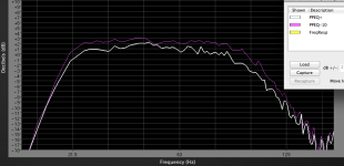
3) As a study of port compression compared to predicted port velocity, though perhaps not an ideal case, it provides useful data. The measurement below using pink noise is more indicative of real world response than the sine wave tests we were looking at. The PPEQ+ curve shows response with the amp just hitting limit (around 2500 watts) using the EQ required to flatten response, including the upper crossover filter. PPEQ-10 is the response with 10 dB less drive level (around 250 watts) raised by 10 dB. Worst case compression appears around 90 Hz, compression in the range where the port's contribution is primary is just over 1 dB.
The "Shoehorn" PPSL2x15" has a Hornresp calculated particle velocity peaking at near 48m/s at 23 Hz, around 34ms at the 40 Hz Fb, falling to around 8m/s at 90 Hz (the slot output reaches a maximum of 16m/s at 18 and 78 Hz). The actual measurements show only one dB compression in the port range over a 10 dB increase in power.
The upper response exhibits more compression, while using only a fraction of the LF power, it appears that calculated particle velocity is not adequate to predict compression effects.
Art
Attachments
Matthew,
A bit of clarification, I tested the Definimax 4015LF in the Keystone, although the FR and sensitivity were quite good, it sounded quite distressed when driven near Xmax, unlike the heavier coned dual Lab 12 and B&C18SW115. BL was not the issue, there was plenty of magnetic force to push the cone into severe breakup, so obvious that I did not even test the distortion, though in retrospect wish I had, just to show how bad it was.
I then postulated that the Kappalite 3015LF, having an even lighter cone (93.4 compared to 139 gram mms) would not be a good choice, even though it may sim OK.
My compliments on designing something a bit different with the Transflex!
Art
I see ! I am surprised that the Definimax failed, it seems like a tough driver, and im sure you are absolutely right when you assume that if the Definimax fails then the Kappalite 3015lf is surely going to fail, horrifically even 😛
Your Keystone apparently has an extraordinary degree of cone control/damping!
Good stuff ...
Working on the ML-Transflex has been a lot of fun , im just getting finished with ironing out the last few bugs on the 135L version for Eminence's Lab-15 (special)...😀
- Home
- Loudspeakers
- Subwoofers
- New sub design? Constricted Transflex, simple build (series tuned 6th order)