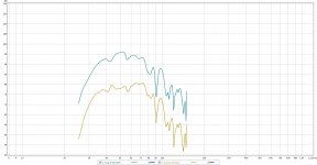
I seem to be getting a bit of that Here are two un-referenced test,the sweeps were done with the same microphone sensitivity, only difference was changing the "playback level". The louder of the two was bloody loud but I didn't check to see if the limiter light went on, don't think it did (oops). There is some EQ applied but it occurs in both sides so can be mostly ignored.
30 Hz shows an increase of 13.2 dB while 49 Hz shows an increase of 17.3
35 Hz shows an increase of 14.71 dB 66 hz shows an increase of 12.5 dB
40 Hz shows 15.8 dB increase. So yeah, take from that what you will.
30 Hz shows an increase of 13.2 dB while 49 Hz shows an increase of 17.3
35 Hz shows an increase of 14.71 dB 66 hz shows an increase of 12.5 dB
40 Hz shows 15.8 dB increase. So yeah, take from that what you will.
Attachments
That looks bloody easy to build, Gonna try that next build. As my picture shows there is some (seemingly) port compression going on at loud output but if anything it flattens the response in my room so I'm not going to worry about it for this build.
P.S. can you make a SWS10d4 (10 inch model) version of that design (assuming it passes AKABAK test) and tell me what angle that flared corner piece makes with the baffle? That way I can throw it in the model.
I just remembered another test using the same cabinet as my prior post, re-used with 15":
http://www.diyaudio.com/forums/subwoofers/255010-compact-2x15-ppsl-using-dayton-pa385-8-drivers.html
The vent velocity in this test was higher than with the Lab 12s, as much higher drive levels were used.
Near Fb, at 40 Hz, going from 63 volts to 89.3 volts, a 3 dB power increase resulted in a 1.8 dB SPL increase, a 1.2 db loss.
At 100 Hz, going from 63 volts to 89.3 volts resulted in a 2.1 dB increase, so "port compression" amounts to only a .3 dB difference.
Now let's get back to this.
This is a very odd choice of designs to study for port compression issues for a couple of reasons. The port is doing very little in this design compared to the driver radiation, and the port is only 6 db down in output at 100 hz compared to it's 40 hz tuning. (The port output is unusually broadband and flat compared to more conventional ported boxes.)
An externally hosted image should be here but it was not working when we last tested it.
That's the port output, the direct radiator output, and the summed total. You can see the direct radiation is about 10 db higher in level than the port output and you can see the port output is only 6 db down at 100 hz compared to 40 hz. You can also see that the port output is still extremely significant higher up in frequency, that thing I circled in red is port output. This is very important because it shows that even up to 320 hz (and higher) the port output is still as high (actually a couple db higher) than in the port only graph.
So this means that the port in this design is doing almost nothing, but the little it is doing it's doing over a very wide bandwidth so 40 and 100 hz will both be very much affected by port compression. In this case it's hard to see the effect of port compression because the tuning is so high, the selected frequencies (40 and 100 hz) are so close, and the compression is occurring over the entire usable bandwidth of the sub.
Usually in a more conventional design the port output at tuning will be a MUCH larger spike (usually 10 db higher than in this design) and much more dominant at lower frequencies than higher frequencies, so the compression looks a lot more dramatic like the pic I posted in my last post.
To see the REAL effect of port compression in this design you need to select frequencies further apart. If you look at 20 hz and 160 hz you have a 0.9 db difference at 20 hz and a 3.3 db difference at 160 hz. (Technically it shouldn't be possible to have a 3.3 db difference but these are your numbers, not mine.)
20 hz 500 watts - 91.5 db
20 hz 1000 watts - 92.4 db
--------------------------
0.9 db difference
160 hz 500 watts - 105.6 db
160 hz 1000 watts - 108.9 db
-----------------------------
3.3 db difference
3.3 - 0.9 = 2.4 db port compression (and there's probably also a bit of compression at 500 watts, so add a bit more)
Again, there are some problems with the 3.3 db figure but these are your numbers. And to be clear, normally we wouldn't have to select frequencies outside the usable bandwidth to see realistic representations of port compression, but in this particular example the tuning is too high and the port output is too weak and too broad in bandwidth to select frequencies as close as 40 and 100 hz to compare.
Ideally a completely different design would be chosen to study port compression, more like the one in my last post. This is a terrible example to study for port compression. It's not a bad design but it's no good for THIS study.
Last edited:
Given that is an active subwoofer, I'll bet that "compression" has a lot more to do with the amp/DSP than the vents. It might be using some sort of dynamic EQ to keep the driver within its linear limits, or some sort of limiting to reduce distortion at high levels (peak current draw will be at Fb). It would explain why the "compression" seems to start way above Fb.
The text I quoted specifically says it's mainly due to port overloading. It's not hard to find pics just like this for passive systems. Also port output is usually much more broadband in real life than in simulations so it's not uncommon to see compression higher than you might expect. (Not usually as broadband as in Art's example though.)
But I get your point, some of it may be the electronics.
P.S. can you make a SWS10d4 (10 inch model) version of that design (assuming it passes AKABAK test) and tell me what angle that flared corner piece makes with the baffle? That way I can throw it in the model.
Saba ,
Thats what i was thinking too ,
I will try to apply this same simplified arrangement to the Alpine boxes to see if it will work out ... 🙂
....
Hey, so I've come to accept that there is some port compression in my alpine box, let's focus the conversation now on if the new design he just came up with could work to fix the issue 🙂.
Also, I may put this out there so people realize where I'm coming from: This design (original purpose) is to provide a lower extension and better sound quality subwoofer (or set) that will fit in a friends compact car and doesn't cost him >1k including amps. That I've achieved and I'm quite happy to live with the designs flaws because I know it will make him smile when he hears them, unlike the reaction I get with every single store bought subwoofer I've heard (portable ones, you know the one's they design to be HP at 45 or higher -- the ones that can't hit 35 for a damn.
Did I mention it's still better than any 10 inch sub I've ever heard, the smallest sub outside of my shitty ones I sold years ago, yet still gets it done.
Alright, back to making a better version for the club lineup I intend to make.
Last edited:
The text I quoted specifically says it's mainly due to port overloading.
I didn't see any evidence in the testing that they checked the output from the amp, so I suspect that was an assumption rather than something confirmed by actual measurement.
The change in response shape looks very similar to what could be expected with DEQ, based on my tests with my NU3000DSP.
In case you guys missed it, post #260 contains a sketch and inputs that may be an improvement in regards to port compression and potential chuff ..
I would like to add something else to this conversation about compression , is it possible that there are many other factors that may be causing compression.. It may be difficult to differentiate in some cases don't you think? BL curves that are not linear for example , as a driver moves further away from it's resting position it can lose some motor strength (BL) , when this happens QES will go up and that can take away from output at the lower cutoff ... Or how about a physical compression where the driver is unable to properly push against the loading of the box , i think Weltersys encountered that when he put a Kappalite 3015lf 15" into his ingenious design the Keystone sub (the incredible loading of the box was just too much for the weak motor in that driver, the light cone may also have been an issue if pushed hard enough) ...... Or how about thermal compression which will also create losses that will be exaggerated in parts of the spectrum where more cone loading/control (physical impedance?) is taking place, it is also due to loss of motor strength via a hot lossy voicecoil and raised RE ....
Seems to me like there could be lots of factors which could create a scenario where the output's frequency response may look different at high power versus low power ... Maybe thats what Brian was getting at earlier ..
Last edited:
In case you guys missed it, post #260 contains a sketch and inputs that may be an improvement in regards to port compression and potential chuff ..
I would like to add something else to this conversation about compression , is it possible that there are many other factors that may be causing compression.. It may be difficult to differentiate in some cases don't you think? BL curves that are not linear for example , as a driver moves further away from it's resting position it can lose some motor strength (BL) , when this happens QES will go up and that can take away from output at the lower cutoff
Excursion is at a minimum at Fb. So compression effects due to the motor or suspension should also be at a minimum at Fb.
Also, if these tests were done with quick sine sweeps, the driver's temperature should not have shifted significantly, which rules out that source of compression as well.
Excursion is at a minimum at Fb. So compression effects due to the motor or suspension should also be at a minimum at Fb.
Also, if these tests were done with quick sine sweeps, the driver's temperature should not have shifted significantly, which rules out that source of compression as well.
Good point , i suppose that rules out a few things.
I am looking at Saba's high/low power graph right now ... The relative bump (or lack of loss?) centered close to 50hz is interesting .... Also , did you guys notice that around 80hz he is only getting a difference of about 10db versus 15-ish db near and just above FB (along with many other areas) ... ? That seems odd ..
According to simulations the port velocity is greatest in the vicinity of FB correct? So it seems that these results are sort of counter-intuitive since he seems to have less loss at around FB when compared to 80hz... hmm .. Should be the reverse if the loss is based upon excess velocity ... What do you suppose that is all about? Anyone?
According to simulations the port velocity is greatest in the vicinity of FB correct? So it seems that these results are sort of counter-intuitive since he seems to have less loss at around FB when compared to 80hz... hmm .. Should be the reverse if the loss is based upon excess velocity ... What do you suppose that is all about? Anyone?
Last edited:
Matthew Morgan,
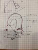
Your sketch shown here:
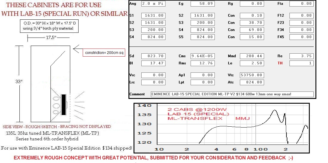
Looks nothing like the dimensions shown in the HR input page, which looks more like this (assuming 16.5 in internal width):
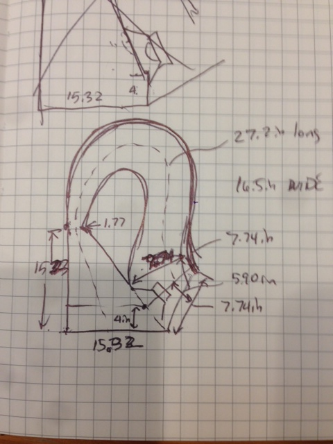
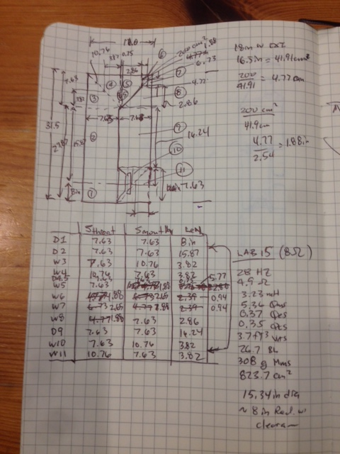
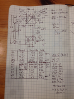
I actually built the Akabak model using your exterior dimensions sketch, which by the way, is more complicated than the last design as it has 12 flow elements vs 9. I deduced all the dimensions based on the 33 in (H) x 17.5 in (D) x 18 in(W), and 200 cm^2 throat (1.88 in x 16.5 in), and practical size of driver puts first segment at 8 in. Here is the sketch of the model based on your sketch:
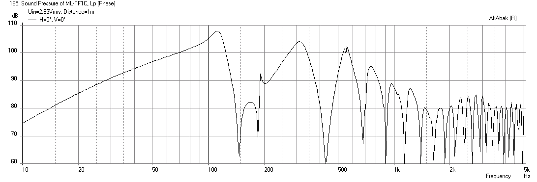
And here is what the predicted response of this box with the 8 ohm LAB 15 (basically, the volume is too small which is why it falls off so fast). Although, I may have a mistake in the code, I doubt it, I double checked the dimensions of the segment per the geometry I derived in the figure above:
You are going to have to do a little more work when it comes to realizing the physical topology given the 4 segments of HR. To build a box that resembles your HR inputs, it will look like my sketch above with the curved horn after the throat. You basically have a BVR (big vent reflex).
Here is the code if anyone feels like double-checking. Also useful if you just want to edit it as the skeleton of the design that is sketched by Matthew Morgan is there:
Your sketch shown here:
Looks nothing like the dimensions shown in the HR input page, which looks more like this (assuming 16.5 in internal width):
I actually built the Akabak model using your exterior dimensions sketch, which by the way, is more complicated than the last design as it has 12 flow elements vs 9. I deduced all the dimensions based on the 33 in (H) x 17.5 in (D) x 18 in(W), and 200 cm^2 throat (1.88 in x 16.5 in), and practical size of driver puts first segment at 8 in. Here is the sketch of the model based on your sketch:
And here is what the predicted response of this box with the 8 ohm LAB 15 (basically, the volume is too small which is why it falls off so fast). Although, I may have a mistake in the code, I doubt it, I double checked the dimensions of the segment per the geometry I derived in the figure above:
You are going to have to do a little more work when it comes to realizing the physical topology given the 4 segments of HR. To build a box that resembles your HR inputs, it will look like my sketch above with the curved horn after the throat. You basically have a BVR (big vent reflex).
Here is the code if anyone feels like double-checking. Also useful if you just want to edit it as the skeleton of the design that is sketched by Matthew Morgan is there:
Code:
| BVR for Lab15 designed by Matthew Morgan L @diyAudio.com
| modeled by xrk971 @diyAudio.com
| Aug 21, 2014
| version ML-TF1C, prototype BVR version

Def_Const
{

| *** these dimensions are used for diffraction/reflection analysis ***
Speaker_pos=8.5*0.0254;  | Height of centerline of exit port above floor
Width_ext=18*0.0254;  | Width of cabinet external
Height=33.0*0.0254; | Height of cabinet external
Depth=17.5*0.0254;  | Depth of cabinet
Dist_wall=5000*0.0254;  | Distance from wall  (70 in gives flat response)

| *** specify internal cabinet panel width here***
Width=16.5*0.0254;  | internal width

}

Def_Driver  'Lab15-8' | 15 in pro sub 8-ohms, Qts 0.35, xmax=11.8mm, xdamage=22mm
  SD=823.7cm2   |Piston
  fs=28.0Hz
  Mms=308g
  Qms=5.36
  Qes=0.37
  Re=4.9ohm
  Vas=104.7L
  Bl=26.7Tm
  Le=3.23mH


System 'ML-TransFlex-C'

| *** Specify high pass and low pass filters here, remove comment bar in front of OFF to turn on

OFF
Filter    'High Pass'  | 4th order Butterworth -24dB/oct
    fo=33Hz  vo=1.0
    {b4=1;
     a4=1;  a3=2.613126;  a2=3.414214;  a1=2.613126;  a0=1;  }
OFF
Filter 'LowPass' |Lowpass filter - 48dB Butterworth (change 'fo=***' and refresh for changes)
fo=100Hz vo=1
{b0=1;
a8=1; a7=5.125831; a6=13.137071; a5=21.846151; a4=25.688356; a3=21.846151; a2=13.137071; a1=5.125831; a0=1; }

| *** specify rear wall loading (assumes only back wall and floor have reflection effect)
|OFF
| Speaker placed in corner with driver at Driver_pos above floor in corner x dist away from walls
Def_Reflector  BottomCorner
Bottom={Speaker_pos}  Left=20in Right=20in
HAngle=0  VAngle=0

| *** specify corner loading (assumes floor and two side walls have reflection effect ***
OFF
| Speaker with driver at Driver_pos above floor Dist_wall away from wall
Def_Reflector  HorizEdge
Bottom={Speaker_pos}  Top={Depth + Dist_wall}
HAngle=0  VAngle=0

Driver Def='Lab15-8' 'Driver 1'  | specify driver here
Node=1=0=11=22  | driver face at node=11, driver back at node=22, amp is node=1, ground is node=0

|  *** begin model of TL ***

Duct    'D1'  Node=10=11  | from closed end to driver face
  WD={Width}  HD=7.63in  Len=8.0in  Visc=1  | Visc=20 used to represent moderate to heavy stuffing

Duct    'D2'  Node=11=12  | from driver to begining of turn
  WD={Width}  HD=7.63in  Len=15.87in  Visc=1

| *** turns modeled as 45 deg expansion followed by 45 deg contraction ***

Waveguide    'W3'  Node=12=13  | first 45 deg turn (expansion)
  WTh={Width}  HTh=7.63in
  WMo={Width}  HMo=10.76in
  Len=3.82in
  Conical
|  AcouResistance    'Stuffing12'  Node=12=13  Ra=7e3Pas/m3  Simulate moderate stuffing

Waveguide    'W4'  Node=14=13  | second 45 deg turn (contraction) note reverse nodes
  WTh={Width}  HTh=7.63in
  WMo={Width}  HMo=10.76in
  Len=3.82in
  Conical
|  AcouResistance    'Stuffing13'  Node=14=13  Ra=70e3Pas/m3  Simulate moderate stuffing

Duct    'D45'  Node=14=15  | divider thickness between turns
  WD={Width}  HD=7.63in  Len=0.75in

Waveguide    'W5'  Node=16=15  | contraction down to restrictor port, ignore thickness of wood, note revers nodes for contraction
  WTh={Width}  HTh=1.88in
  WMo={Width}  HMo=7.63in
  Len=5.75in
  Conical

Waveguide    'W6'  Node=16=17  | 45 deg turn of constrictor corner expansion
  WTh={Width}  HTh=1.88in
  WMo={Width}  HMo=2.65in
  Len=0.94in
  Conical

Waveguide    'W7'  Node=19=18  | 45 deg turn of constrictor corner contraction, note reverse nodes
  WTh={Width}  HTh=1.88in
  WMo={Width}  HMo=2.65in
  Len=0.94in
  Conical

Waveguide    'W8'  Node=19=20  | Expansion from constrictor to main downward duct
  WTh={Width}  HTh=1.88in
  WMo={Width}  HMo=7.63in
  Len=5.75in
  Conical

Duct    'D9'  Node=20=21  | Main downward duct to mouth
  WD={Width}  HD=7.63in  Len=16.24in

| *** driver backside at node=22 ***
Waveguide    'W10'  Node=21=22  | 45 deg turn, expansion from duct to corner of mouth
  WTh={Width}  HTh=7.63in
  WMo={Width}  HMo=10.76in
  Len=3.82in
  Conical

Waveguide    'W11'  Node=23=22  | 45 deg turn, contraction from corner to mouth, rad at node=23
  WTh={Width}  HTh=7.63in
  WMo={Width}  HMo=10.76in
  Len=3.82in
  Conical

| *** specify radiator as exit node of final mouth duct ***

Radiator 'Duct_rad'
Def='W11'
Node=23
| *** comment out following lines if no baffle diffraction desired and no reflections desired
x=0  y=0  z=0
HAngle=0  VAngle=0
WEdge={Width_ext/2}  Hedge={Height}
Reflection
Attachments

Last edited:
... let's focus the conversation now on if the new design he just came up with could work to fix the issue 🙂
In case you guys missed it, post #260 contains a sketch and inputs that may be an improvement in regards to port compression and potential chuff ..
I have to ask what is the point of the constriction? Is it just for the sake of doing a new and different design concept? Besides the novelty aspect it doesn't really seem to outperform other alignments that are easier sim, easier to lay out and easier to build and have no constrictions.
For example here's a simple reverse taper offset tl. It's not a particularly good tl but I tried to follow the response shape as closely as possible to the design I was emulating, the one in post 260 and I'm not sure which features are desired. I think someone mentioned that the bump down near tuning and was cool as well as a bit of a saddle. (The low knee bump in mine is a bit higher in frequency but it could be lowered with a bit of redesign or a bit of eq.) I also kept the spike up higher, slightly out of a sub's normal bandwidth. Not sure why you would want that but it's there. I think mine is 5 liters larger. I used CON segments because the design in post 260 did, which isn't right but it makes for a fair comparison.
I showed both at the same power input (the constricted design is in light grey) and the simple tl outperforms the constricted design at all frequencies between about 38 and 140 hz and it does it with less excursion. Mine is tuned a couple hz higher though, so all in all they are about even, louder/lower cancels out. This is a 5 minute sim and it could definitely be improved, so you can see you don't need a constriction for any reason that I can see. AFAIK Brian used the dogfood constriction because it fixed something he didn't like in an existing design, I'm not sure it's the best idea to use it as an exclusive design feature for a new design.
I also included the graph for vent velocity for my simple tl. Flare It says my port is plenty large enough, by the Flare It standard I could reduce it quite a bit but I prefer not to, in fact I would prefer it to be larger but there's only so much you can do with the goals I was trying to achieve here - mainly to emulate the design in post 260 as closely as possible with a simpler design.
Anyway, I realize I've nitpicked everything here to death and I do apologize for that because I really do appreciate the innovation and enthusiasm going on here but I can't see any good reason to use a constriction if you don't have to and I just wanted to let you know IMO it's not a good idea.
An externally hosted image should be here but it was not working when we last tested it.
Matthew Morgan,
"I actually built the Akabak model using your exterior dimensions sketch, which by the way, is more complicated than the last design as it has flow elements vs 9."
"And here is what the predicted response of this box with the 8 ohm LAB 15 (basically, the volume is too small which is why it falls off so fast). Although, I may have a mistake in the code"
.
Hey there XRK ,
According to your hand written sketch that does look like work , thanks for putting this into Akabak .... 130 or 135 liters is enough volume for the Lab 15 , but i think it might not be clear about how the HR sim relates to the sketch .... The throat chamber has no port attached to it so it is basically just a big chamber with an open end that comprises the first 2 feet of the path which the S1 through S5 connect to... The path then proceeds to S1 & S2 which open up to a large area as it goes around the turn (the reason for the large cm sq area of S2) , then a squeezed down S3 creates the constriction , then below that there is another 30+ inches of path ..... It certainly works well with HR , not sure why it isn't translating to Akabak...
You are right that it is similar to a BVR , or even a Cubo but this box will have more quarter wave action because of it's longer path length , Cubos have a pretty short path 🙂
One thing that comes to mind is that since the pressure end of a classic quarter wave resonator is located at the closed end, and the max velocity end of the pipe is the mouth/terminus i would imagine that moving the constriction up the path (away from the mouth) could cut down on velocity since it is no longer the end anymore (the smaller segment does contribute to path length) which sets this design apart from any standard ML-TL
Yeah, it’s not a vent, it’s just a stepped open pipe segment connecting a larger closed pipe and reflex compression chamber, so its air mass ‘slug’ is trapped between two mismatching acoustical impedance junctions. In this context we can view it from the reflex side as the initial expansion in a BLH, ergo all we need to do in theory is taper it slightly, but in reality it’s well proven that using relatively short lengths of straight pipes laid out in multiple bends like Olson did with his BLH only rolls off unwanted HF content.
All this ‘hand waving’ over ‘chuffing’, high vent velocity = distortion seems irrelevant to me as it’s going to be damped by the two segments it connects to.
FWIW, using Prof. Leach’s math, I get a ~76.52 cm^2/11.86”^2 ‘vent’ pipe, so had I done your alignment this is what I would have used.
If sustained high power apps compression is the primary concern, then increase its area/length to lower its compression ratio lest it maybe damage the driver; otherwise, ‘much ado about nothing’ to my way of thinking.
GM
I am looking at Saba's high/low power graph right now ... The relative bump (or lack of loss?) centered close to 50hz is interesting .... Also , did you guys notice that around 80hz he is only getting a difference of about 10db versus 15-ish db near and just above FB (along with many other areas) ... ? That seems odd ..
According to simulations the port velocity is greatest in the vicinity of FB correct? So it seems that these results are sort of counter-intuitive since he seems to have less loss at around FB when compared to 80hz... hmm .. Should be the reverse if the loss is based upon excess velocity ... What do you suppose that is all about? Anyone?
Everything about those measurements (in relation to each other) is weird. I don't think there's anything to learn from these. Proper measurements need to be done outside ideally, at clearly indicated power levels.
If the sub, or the mic, or an object in the room moves a couple of inches this kind of thing can happen. And without a calibrated measurement or any indication of power level it's impossible to really know what's going on.
Yeah, it’s not a vent, it’s just a stepped open pipe segment connecting a larger closed pipe and reflex compression chamber, so its air mass ‘slug’ is trapped between two mismatching acoustical impedance junctions. In this context we can view it from the reflex side as the initial expansion in a BLH, ergo all we need to do in theory is taper it slightly, but in reality it’s well proven that using relatively short lengths of straight pipes laid out in multiple bends like Olson did with his BLH only rolls off unwanted HF content.
All this ‘hand waving’ over ‘chuffing’, high vent velocity = distortion seems irrelevant to me as it’s going to be damped by the two segments it connects to.
FWIW, using Prof. Leach’s math, I get a ~76.52 cm^2/11.86”^2 ‘vent’ pipe, so had I done your alignment this is what I would have used.
If sustained high power apps compression is the primary concern, then increase its area/length to lower its compression ratio lest it maybe damage the driver; otherwise, ‘much ado about nothing’ to my way of thinking.
GM
All this hand waving was over compression, not chuffing, I think I mentioned that about a dozen times. Port compression is distortion. If you think there's enough compression near the end of the line in the low pressure high velocity end of the box to destroy the driver I can't see how this isn't an issue.
I'm not familiar with Olson's stepped blh but if it's like all other stepped blhs, the small ducts are in the throat, the low velocity part of the horn, and he probably used very low xmax drivers so this isn't anything close to the initial expansion in an antique blh.
Last edited:
- Home
- Loudspeakers
- Subwoofers
- New sub design? Constricted Transflex, simple build (series tuned 6th order)