Hi sabaspeed521,
Post #295: "Could someone tell me what topology this is?"
Your Hornrespsimulation is a pipe w/ the driver on one end of the pipe, the pipe folded around, and the other side of the driver on the other end of the pipe. It might be hard to come up w/ a geometry that satisfies the L12=L34=0.10cm condition.
I'll attach a quick TH simulation using your T/s parameters. Naturally, that is not what this thread seems to be all about.
Regards,
Attachments
JAG,
The "Shoehorn" PPSL2x15" has a Hornresp calculated particle velocity peaking at near 48m/s at 23 Hz, around 34ms at the 40 Hz Fb, falling to around 8m/s at 90 Hz (the slot output reaches a maximum of 16m/s at 18 and 78 Hz). The actual measurements show only one dB compression in the port range over a 10 dB increase in power.
Art
So even at those velocity rates the compression was pretty insignificant according to what you are saying , and im assuming there was no audible chuffing, correct? 😉
The upper response exhibits more compression, while using only a fraction of the LF power, it appears that calculated particle velocity is not adequate to predict compression effects.
Art
That was exactly the impression i was getting from looking at Saba's graphs since maximum port velocity is supposed to be highest down near FB, but that is certainly not where we were getting the highest degree of compression ... He was getting more compression effects up around 80hz which completely contradicts the simulated velocity graphs ..... If more measurements happen to show the same trend over and over again then i would have to become suspicious about a possible flaw in the "official" understanding of how these things truly work ...
Hi sabaspeed521,
Post #295: "...convert designs from hornresp into a folded entity. Anyone have any good resources for that."
Here are some very good starting points:
Simple Tapped Horn Tutorial using Hornresp - AVS Forum
Hornresp for Dum... hmm... Everyone 😉 - Home Theater Forum and Systems - HomeTheaterShack.com
Horn Folding in Sketch-Up - AVS Forum
Regards,
First off, the l12 and l45 are the 0.1 cm one's (not 34) but more importantly: part of the problem is I don't know what all the L12 L34 and what not correlate to, trying to read up now but it seems that those two numbers can be varied without messing the response up much up to say roughly 10 cm.Hi sabaspeed521,
Post #295: "Could someone tell me what topology this is?"
Your Hornrespsimulation is a pipe w/ the driver on one end of the pipe, the pipe folded around, and the other side of the driver on the other end of the pipe. It might be hard to come up w/ a geometry that satisfies the L12=L34=0.10cm condition.
I'll attach a quick TH simulation using your T/s parameters. Naturally, that is not what this thread seems to be all about.
Regards,
How I understand the extremely basic design I put up.
For my design idea I assume s1 -s5 correspond to the cross sectional volume of the pipe which since I'm keeping it constant in this case to minimize turbulence means they are the same. I generally assume that l23 and l34 which I set to 120 cm make up the front and rear halves of the pipe and that l12 and l45 somehow correlate to the ends? Is there a picture out there that shows all the "segments" that hornresp is talking about for a generic pipe? I can only find some documents detailing horns.
While that hometheatershack thread is really informative, I'm still having difficulties seeing which of "those designs" is close to a folded (non-tapered) pipe that I'm proposing. I'll try drawing a side view of what I think I'm simulting and you guys can hopefully tell me what's wrong with it.
1) "Horrific fail", pretty strong terms- if we look at the Keystone thread at only 271 posts compared to the SS15 thread at 2069 posts, the Keystone is 8.8 dB down ;^).1) I am surprised that the Definimax failed, it seems like a tough driver, and im sure you are absolutely right when you assume that if the Definimax fails then the Kappalite 3015lf is surely going to fail, horrifically even.
Your Keystone apparently has an extraordinary degree of cone control/damping!
2)So even at those velocity rates the compression (in the Shoehorn PPSL) was pretty insignificant according to what you are saying , and im assuming there was no audible chuffing, correct? 😉
3)That was exactly the impression i was getting from looking at Saba's graphs since maximum port velocity is supposed to be highest down near FB, but that is certainly not where we were getting the highest degree of compression ... He was getting more compression effects up around 80hz which completely contradicts the simulated velocity graphs ..... If more measurements happen to show the same trend over and over again then i would have to become suspicious about a possible flaw in the "official" understanding of how these things truly work ...
Lightweight cones work fine under the lower pressures in a BR, but may not be up to the task in designs that leverage output by 6 dB, though it does not seem to bother people that that 6 dB increase may be lost at actual use level:
In post # 1492, “Single sheet TH challenge”, Crescendo measured his 3015LF loaded, 1/2” Aruco plywood SS15 cabinets outdoors: 70Hz: 103.2 dBC, 2.83 v at one meter, 70Hz, 124.7dBC, QSC PLX3402 amplifier “just at clip” (about 75 volts, 700 watts at 8 ohm). Had there been a linear voltage in/SPL out relationship, 700 watts/75 volts would have resulted in about a 28.5 dB increase in SPL, 131.7 dBC.
131.7-124.7 = 7 dB of power compression. Ouch.
The BC18SW115-4 Keystone hardly has any power compression, and a fraction of the distortion of a lightweight cone driver in the SS15, but few seem to notice those pesky details 🙂.
2) Yes, I'd rate a 1-2 dB compression over a 250-2500 power range as pretty insignificant. In my notes I wrote the Dayton PA385S-8 venting design gets rid of the voice coil heat very effectively with very little noise, but did not mention port noise, I don't recall if port noise was completely absent, or simply not heard over the level of the cabinet reaching around 130 dB at a meter.
3) Saba's indoor response curves may not be indicative of the actual cabinet response at different levels, I would not make any speculations unless outdoor tests away from boundaries showed similar response deviations.
Art
Matthew Morgan,
"I actually built the Akabak model using your exterior dimensions sketch, "
"You are going to have to do a little more work when it comes to realizing the physical topology given the 4 segments of HR. "
[/CODE]
XRK ,
I put something together or you , maybe it will help you with the Akabak modeling.. ....
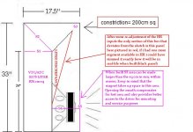
I used more than just the four segments because i also used a giant throat chamber to form the first portion of the path .... I added highlighted notes to the sketch which show how the Hornresponse segments and chambers correspond with the actual parts of the cabinet as it would be built ....
I was also able to adjust Hornresponse to more closely approximate the dilation in the path (S2) just before the constriction (s3) , it really didn't change the response too much but at least it matches the sketch more closely now..
On my brightly colored sketch notes, the red text and red depiction explain the one shortcoming of HR to sim this box, i would need one more segment to fix this area in order to match the sketch perfectly .. So that last section shows a longer portion of pipe with expansion in HR when in reality it should be a shorter area with expansion followed by a straight segment with no expansion which then leads to the mouth/exit ...... This accounts for the discrepancy in volume seen in HR versus the box's outer dimensions ... The actual built box wont have any wasted space internally, and the slight downward shift in FB caused by the altered contour of the S3-S4 segment can be offset by making the mouth/terminus large enough to have easy access to the driver ... So it should all work out well ! 😀 It still would be nice to have an Akabak confirmation though , just to be diligent🙂
Attachments
Last edited:
I am feeling pretty good about this updated Lab 15 (special run) ML-Transflex design now, it has a flared vent, and the velocity in this Eminence box is now lower putting it within the same range as the Alpines in the earlier style of the ML-Transflex cabs like Saba built, and according to the feedback we are getting from Saba it looks like neither chuffing nor port compression are really much of an issue at all with these boxes even at these power levels (250w for the Alpine and 600w for the Eminence in the bigger box) =)
Now, perhaps i will try to adapt this same thing to the smaller Alpine box to update it and lower the simmed velocity on that one as well .....
Now, perhaps i will try to adapt this same thing to the smaller Alpine box to update it and lower the simmed velocity on that one as well .....
JAG,
1) The Hornresp simulated output of the port below 50 Hz is louder than the radiation from the slot (Horn). The port output at 100 Hz is around 16 dB less than the radiation from the slot. The excursion minima at Fb allows a large EQ boost without over excursion, not possible in a sealed enclosure with similar raw response.
2) Ideally, a test of Mathew Morgan's Transflex design would be conducted at various levels to determine if the constriction leads to a compression issue.
3) As a study of port compression compared to predicted port velocity, though perhaps not an ideal case, it provides useful data. The measurement below using pink noise is more indicative of real world response than the sine wave tests we were looking at. The PPEQ+ curve shows response with the amp just hitting limit (around 2500 watts) using the EQ required to flatten response, including the upper crossover filter. PPEQ-10 is the response with 10 dB less drive level (around 250 watts) raised by 10 dB. Worst case compression appears around 90 Hz, compression in the range where the port's contribution is primary is just over 1 dB.
The "Shoehorn" PPSL2x15" has a Hornresp calculated particle velocity peaking at near 48m/s at 23 Hz, around 34ms at the 40 Hz Fb, falling to around 8m/s at 90 Hz (the slot output reaches a maximum of 16m/s at 18 and 78 Hz). The actual measurements show only one dB compression in the port range over a 10 dB increase in power.
The upper response exhibits more compression, while using only a fraction of the LF power, it appears that calculated particle velocity is not adequate to predict compression effects.
Art
We both agree that this isn't the best design to study port compression but this new measurement only serves to cloud the issue further. With eq and filters and possibly other dsp at play it's almost impossible to know what's going on. Since there's no compression at low frequencies at all I assume there's high pass filter in place. That skews everything.
Hornresp won't allow you to check velocity with a hpf in place (that I know of) so I exported to Akabak and ran the sim with no filter (should look just like your Hornresp velocity sim) and then I added a 35 hz 4th order butterworth filter. (Just a guess.)
An externally hosted image should be here but it was not working when we last tested it.
Big difference. So it's back to Flare It to see what it says. It says at 35 hz you are safe to 15 m/s with your combined port size. At 40 hz it's assumed that you are safe up to about 18 m/s. So with a 35 hz hpf in place your ports are not as undersized as you might think. (They are clearly too small to be ideal though, there is almost 2 db of compression visible at 31.5 hz even with the hpf in place.)
A 35 hz hpf might be a bit too aggressive, 30 hz might be more appropriate, but even then you are peaking at 31 m/s. This is a far cry from the constricted design that I ran the sim on, with 26 m/s estimated velocity with hpf in place and a 9 m/s safety rating from Flare It.
I... according to the feedback we are getting from Saba it looks like neither chuffing nor port compression are really much of an issue at all with these boxes even at these power levels (250w for the Alpine and 600w for the Eminence in the bigger box) =)
I don't think he ever said that compression wasn't an issue and even if he did there's no way to determine that without proper measurements.
Check my last post, even Weltersys's box has significant compression (and just because he doesn't mind losing a couple of db doesn't mean it isn't significant) and his ports are quite a bit more appropriate (according to Akabak and Flare It) than the box Saba built.
I don't want to keep nitpicking but proper measurement are required before you can determine how much (not if) compression is affecting things.
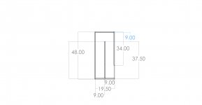
Rather than talking about the small alpine box can you guys critique this "big" straight pipe alpine box and label the respective hornresp parameters on this side view?
I have the full model in solidworks for the alpine sws15d4 and was hoping folks could comment on how I can make the hornresp match the drawing.
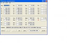
Here is what I tentatively have as inputs (image 2)
How can we make this simple alpine pipe into something a bit more compact like the lab 15 design in such a way that it doesn't exhibit port compression and is still easy to build?
Maybe we can see if a slightly flared shorter version of this could work.
Attachments
Last edited:
JAG,With eq and filters and possibly other dsp at play it's almost impossible to know what's going on. Since there's no compression at low frequencies at all I assume there's high pass filter in place. That skews everything.
Not impossible to know what's going on in the response curves posted in #299, the filters used were from a DBX DriverackPA set as follows: 24BW 30 Hz HP, 106 Hz LP, 31.5+6 dB,Q.2.63,60Hz-7, 2.03Q. The DRPA is not capable of dynamic EQ (EQ that varies in amplitude at different frequency) which would skew results if it were used.
The measurement was taken just at the illumination of the Speakerpower SP4000 clip light on peaks using the Smaart pink noise output, then turned down 10 dB on the DRPA output.
A simple high pass filter and corrective EQ as would be used by any competent user does not skew anything regarding measurement of compression. There was a bit of compression at both the lower and upper end (more at the upper end) of the pass band, but as you noticed, where virtually no power was presented to the speaker due to the steep Butterworth HP, there was no compression.
Considering the amount of LF boost near the impedance minima, I was quite pleased with the lack of compression the Dayton PA385S-8 drivers exhibited in the "Shoehorn" alignment.
Art
Last edited:
Rather than talking about the small alpine box can you guys critique this "big" straight pipe alpine box and label the respective hornresp parameters on this side view?
I have the full model in solidworks for the alpine sws15d4 and was hoping folks could comment on how I can make the hornresp match the drawing.
Here is what I tentatively have as inputs (image 2)
How can we make this simple alpine pipe into something a bit more compact like the lab 15 design in such a way that it doesn't exhibit port compression and is still easy to build?
Maybe we can see if a slightly flared shorter version of this could work.
S1 is the throat, S2 in the driver center point a few cm past the throat, S3 is the mouth. You could break that up into more segments if you wanted but those are necessary. That's really all that's shown there.
There are a few tutorials on this. Soho54 made all kinds of pictures to explain everything if you can find his tutorials and posts.
Rather than talking about the small alpine box can you guys critique this "big" straight pipe alpine box and label the respective hornresp parameters on this side view?
I have the full model in solidworks for the alpine sws15d4 and was hoping folks could comment on how I can make the hornresp match the drawing.
Here is what I tentatively have as inputs (image 2)
How can we make this simple alpine pipe into something a bit more compact like the lab 15 design in such a way that it doesn't exhibit port compression and is still easy to build?
Maybe we can see if a slightly flared shorter version of this could work.
Saba ,
That is a classic tapped pipe or Transflex (or JBL Air coupler) ... It is basically a tapped TL (or more specifically a tapped "QWP") and it can work very well if everything fits and the driver's parameters are appropriate for such an alignment ...
It is very easy to simulate in Hornresponse and easy to build... I can post the inputs if you like ...
It was actually the first thing i tried for the Lab-15 but the footprint was a bit too small for that driver in my opinion so that is what prompted the need for the constricted version, in order to shorten the line by a bit and allow a bigger footprint with less height.
Another option (as JustaGuy suggested) is to use a reverse taper, that also allows a reduction in path length and a larger footprint, yet a nice compact box ....
There are many ways to skin a cat as they say (what a horribly sadistic saying that is , who came up with that?!? 😛)
Last edited:
JAG,
Not impossible to know what's going on in the response curves posted in #299, the filters used were from a DBX DriverackPA set as follows: 24BW 30 Hz HP, 106 Hz LP, 31.5+6 dB,Q.2.63,60Hz-7, 2.03Q. The DRPA is not capable of dynamic EQ (EQ that varies in amplitude at different frequency) which would skew results if it were used.
The measurement was taken just at the illumination of the Speakerpower SP4000 clip light on peaks using the Smaart pink noise output, then turned down 10 dB on the DRPA output.
A simple high pass filter and corrective EQ as would be used by any competent user does not skew anything regarding measurement of compression. There was a bit of compression at both the lower and upper end (more at the upper end) of the pass band, but as you noticed, where virtually no power was presented to the speaker due to the steep Butterworth HP, there was no compression.
Considering the amount of LF boost near the impedance minima, I was quite pleased with the lack of compression the Dayton PA385S-8 drivers exhibited in the "Shoehorn" alignment.
Art
Yeah, it's not impossible if you tell me what's going on. The fact that a hpf was used but not mentioned does make a big difference as I showed in the last image I posted. Filtering out the low bass makes a huge difference with velocity and compression. You said:
The "Shoehorn" PPSL2x15" has a Hornresp calculated particle velocity peaking at near 48m/s at 23 Hz, around 34ms at the 40 Hz Fb,
... and while that might be true in the Hornresp sim that's not even close to accurate in the real world with the hpf in place. So when you use that as a basis to say that "it appears that calculated particle velocity is not adequate to predict compression effects.", it appears that you neglected to account for the hpf. With the hpf the calculated particle velocity and port size creates the amount of compression you should expect to see.
I ran a 24BW 30 Hz HP already. As I mentioned peak velocity with that filter in place is 31 m/s, Flare It says 18 m/s is safe at 40 hz. So none of your measurements are surprising.
Like I said, it's not a bad design, it lives up to it's fairly unique design goals quite well, and it exhibits the amount of compression you would expect to find with moderately undersized ports.
Last edited:
Saba ,
That is a classic tapped pipe or Transflex (or JBL Air coupler) ... It is basically a tapped TL (or more specifically a tapped "QWP") and it can work very well if everything fits and the driver's parameters are appropriate for such an alignment ...
It is very easy to simulate in Hornresponse and easy to build... I can post the inputs if you like ...
It was actually the first thing i tried for the Lab-15 but the footprint was a bit too small for that driver in my opinion so that is what prompted the need for the constricted version, in order to shorten the line by a bit and allow a bigger footprint with less height.
Another option (as JustaGuy suggested) is to use a reverse taper, that also allows a reduction in path length and a larger footprint, yet a nice compact box ....
There are many ways to skin a cat as they say (what a horribly sadistic saying that is , who came up with that?!? 😛)
That would be great if you could post the inputs, I think the alpine 15 should work for that kind of alignment.
Sidenote: why couldn't you just make the box deeper to accomodate the lab 15? I see no reason why you couldn't do that.
S1 is the throat, S2 in the driver center point a few cm past the throat, S3 is the mouth. You could break that up into more segments if you wanted but those are necessary. That's really all that's shown there.
There are a few tutorials on this. Soho54 made all kinds of pictures to explain everything if you can find his tutorials and posts.
Found this thanks to another forum member
Hornresp for Dum... hmm... Everyone 😉 - Home Theater Forum and Systems - HomeTheaterShack.com
But it doesn't talk about t-qwt.
S1 is the throat, S2 in the driver center point a few cm past the throat, S3 is the mouth. You could break that up into more segments if you wanted but those are necessary. That's really all that's shown there.
There are a few tutorials on this. Soho54 made all kinds of pictures to explain everything if you can find his tutorials and posts.
As these are areas, where is S2 vs S1, what do you mean by a few cm past the throat? The whole pipe is the throat...
Just trying to make sure I get what you're saying.
The examples I see by google searching tqwt all are "tapered quarter wave tubes" and as is mine isn't tapered at all, I'm open to looking into that but I'm not sure how to "set the taper" if you will. Will do more research.
Last edited:
Here's a few images from google image search. None of these are straight pipes like yours but this shows how the Hornresp input markers line up with the physical parts in different designs. The 2nd pic is a tapped horn, so just change the segment shapes a bit so all the segments are equal csa and that's it. Horn folding is a whole other ballgame, there are many ways to do it and you already had a few links posted for you. Advanced centerline method is more accurate than centerline method or the Sketchup tutorial method.

An externally hosted image should be here but it was not working when we last tested it.
Last edited:

- Home
- Loudspeakers
- Subwoofers
- New sub design? Constricted Transflex, simple build (series tuned 6th order)