I was going to suggests putting trimpot locations on both edges but didn't think that was easily doable with all of the other traces on the boards. I suppose you could use jumpers to go over the other traces and decide which trimpot location you want to be in use.Hi Zen Mod, I don't know what size your FE boards were. The one Nelson laid out was 3.5"x5.5", which put it in the $65 with shipping for 10 pieces.
Hi Mike, I don't think I can change the gerbers from another package though I have never tried to import them (maybe I will have to look into that), I just use the schematic capture and PCB layout program to make new boards. On the new board I am making, it fits between the current long screws which are on a 2.75"x 4.25" pattern. I laid out the PCB to use the 220uf Silmics for C2 and C3. Also I like to use multiturn pots that can be had with the screw on the top or on the side, and you can reverse them, so they can face up or down, and I always try to put them near the edge of the board so easier to adjust, and if possible make a location on both edges so you populate whichever one you want up. I design stuff from the point of easier to service if I can. Too many times working on my car I wanted the Toyota engineers throat in my hands. 🙂
I have a LS400. Someday it will need a Timing belt... Was easy doing it on a Tundra but the LS400 is very tight... BTW, ford and Chevy are far worse.
I thought I had gone through the entire thread but I missed the size of the ZM board, Nice work. Now I will have to see what I want to build.
So, time to re-read the thread for fun. 🙂
So, time to re-read the thread for fun. 🙂
So going back to my post in #1257 I learned a few things. I believe the NTC thermistor takes the bias and lowers it as the transistors come up to temp. I also learned that my bias issue was due to C4 being empty. As of right now, I have 20pf in there.
Increasing R18 resulted in very high bias, to the point where it would blow the negative rail fuse (I put 2 amp fuses in for testing). Lowering R18 resulted in lower bias and less of a rise. With 20pf oscillator cap in place, the bias behaves. Also, taking the cover off causes the bias to drift. So as Zen Mod says, put the amp together. I believe I need to increase C4 a bit more. I will grab a 25pf, 30pf and a 35 and try them. I need to get something that produces an accurate square wave though. At 10khz, my DAC seems to put out a sine wave according to my oscilloscope.
I also was able to fit the 220uf Silmic II cap in C2. I just bent it over.
When I get everything wrapped up. I will post a schematic with the values that I have in place. Also pictures showing everything as best as I can.
Now that I have the amp behaving a bit more, I put in my system and gave it a listen, the amp is extremely detailed.
Quick question for you vets, using a 800va transformer with maybe ~300mf of capacitance on a CLCLC, is a thermistor like a cl60 or cl80 cool or should a thermistor be avoided and the store soft start board be used? I actually may have time to resume building this bad boy. Something that should have been a weekend build has turned into year long endeavor
Last edited:
For managing in-rush current for a transformer and capacitance bank of that size, a larger thermistor will be necessary. I recommend the Ametherm MS22 20005. It has a higher initial resistance and greater current handling capacity. Also more surface area to manage the power dissipation.

You the man, thank you!For managing in-rush current for a transformer and capacitance bank of that size, a larger thermistor will be necessary. I recommend the Ametherm MS22 20005. It has a higher initial resistance and greater current handling capacity. Also more surface area to manage the power dissipation.
How's life been treating you these days; good i hope?
decided to rejoice some of my Yore amps with Hitachi laterals
BC639/640 instead of ZTX
MJE340/350 instead of 2SA/SC
see what I'm doing for pico-caps, lazy to search and order through-hole, already having drekload of them in SMD
will post, once when done, actual schematic and some pics
when - who knows, that's lazy work
BC639/640 instead of ZTX
MJE340/350 instead of 2SA/SC
see what I'm doing for pico-caps, lazy to search and order through-hole, already having drekload of them in SMD
will post, once when done, actual schematic and some pics
when - who knows, that's lazy work
Attachments
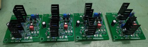
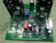
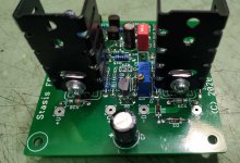
Fantastic SMD implementation.decided to rejoice some of my Yore amps with Hitachi laterals
BC639/640 instead of ZTX
MJE340/350 instead of 2SA/SC
see what I'm doing for pico-caps, lazy to search and order through-hole, already having drekload of them in SMD
will post, once when done, actual schematic and some pics
when - who knows, that's lazy work
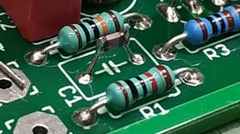
how do you keep the SMD from unsoldering when you solder add-on legs
to the PCB? Forceps as a heat sink? -nice work around- 🙂
to the PCB? Forceps as a heat sink? -nice work around- 🙂
Any reason for the substitutes? Just what was handy?BC639/640 instead of ZTX
MJE340/350 instead of 2SA/SC
how do you keep the SMD from unsoldering when you solder add-on legs
to the PCB? Forceps as a heat sink? -nice work around- 🙂
U shape leftover pin of 1N4148, solder in pcb, cut U above, refresh soldering on cap itself
if you're soldering properly in pcb, that is not going to melt solder at cap
Any reason for the substitutes? Just what was handy?
exactly
most of declared parts are for wrong side of Ocean, while I'm living on proper side of Ocean

Last edited:
I plan on building monoblocks, each one using 1 + 5 + 5 deep as referred to at post #185 by ZM. I will use 2SA1294 / 2SC3263.
My goal is to directly drive sub 1 ohm impedance ribbons and so I need to maximise the output current capability. Can someone please advise me on what power supply specs I should be aiming for and any other pointers given my objective. TIA.
My goal is to directly drive sub 1 ohm impedance ribbons and so I need to maximise the output current capability. Can someone please advise me on what power supply specs I should be aiming for and any other pointers given my objective. TIA.
for that ....... minimized rails voltage, whatever you build
also maximized number of outputs, whatever you build
Pa will tel you how good candidate Stasis is for that
why not finding proper autoformers for that setup (dunno how big task is that, to find them) so you have much easier choice of amp?
also maximized number of outputs, whatever you build
Pa will tel you how good candidate Stasis is for that
why not finding proper autoformers for that setup (dunno how big task is that, to find them) so you have much easier choice of amp?
People who have tried directly driving them report big improvements in sound quality, so I’m keen to try it.for that ....... minimized rails voltage, whatever you build
also maximized number of outputs, whatever you build
Pa will tel you how good candidate Stasis is for that
why not finding proper autoformers for that setup (dunno how big task is that, to find them) so you have much easier choice of amp?
Do the OS boards need to be close together? If not I could add a second heatsink (I’m making my own chassis) and put 1+5+5 on one heatsink and another +5 on a second (opposite) heatsink, or even +5 +5 on the second heatsink - ?
you can have separate OS boards at separate sinks
you did observe well that you don't necessary need drivers installed on secondary OS pcb, just actual OS transistor
now, only you can tell difference between amp driving ribbon directly, or amp being lesser strained, working through proper autoformer
that's just outcome what's ( generally, and for you ) sum of steps positive and steps negative .......... though, we - couch experts, we can advise you perfectly till the end of time ( and back) , your opinion is irrelevant
Thanks ZM. So being able to spread the OS boards across 2 sinks means I could daisy chain 4 of them and have say 1+5+5+5+5 in one monoblock. That would hopefully mean that the amp is not strained and there are only benefits from driving direct.
why not
though, no need to go above, say, 18-20Vdc rails, maybe even lower
but, in yor boots, I would go with square law OS with mosfet pucks
one pair of these can do wonders
though, no need to go above, say, 18-20Vdc rails, maybe even lower
but, in yor boots, I would go with square law OS with mosfet pucks
one pair of these can do wonders
Okay, so I messed around with trying to swap the front end with the values suggested earlier in this thread for my Threshold S/500. It was prone to oscillation. I tried a variety of caps and got it to behave and bias okay. Not great but just okay. Taking the top off of the chassis would cause the bias to start going up. The oscillation cap seemed too high as it was causing the soundstage to dissapear but the center image was very strong. However, it didn't sound quite right. I suspect this front end wasn't intended for the 80v rails that the stock S/500 has.
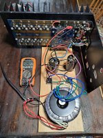
So an experiment. I bought two 500va 30v transformers. I mocked up a little power supply to test (40v rails, no CRC filter, a fuse, and about 100000uf). The nice thing about this is I can now run the stock values that the front end was initially designed with since the rails are now 40vdc. I will run dual mono with the DIYaudio CRC network and the onboard rectifier section. I suspect this will get me down to around 39vdc. I checked to see that the S/500 runs the same output devices that the SA/1 runs. It does. So I should end up with around 70-80 watts or so in pure class A per channel. This should hopefully make for a neat hotrodded SA/2.5ish?
I am powering up the amp tonight with my cheesy test power supply just to test and see that things behave, stay cool, bias up without smoking etc. Tomorrow, I intend to go through the new stassis front end board and return all of the values back to stock. Then I can bias it up again and hook up a minimus 7 to it (test speaker)
I am excited to see if it sounds better than the original setup. Worst case scenario, I can return the S/500 back to stock and make a stassis amp in a different chassis. I'll have most of the parts anways.
Now I am debating whether to stuff everything in the original chassis or if I should run a separate power supply case and put some extra caps in the main chassis.
Attachments

- Home
- Amplifiers
- Pass Labs
- New Stasis front end