One channel is alive! I Played it for a while then a LaScala. Initial impressions are that it is dead silent sitting on the bench, no hum.
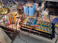
On the S/500, and I assume other Threshold amps, the mounting studs for the front end board is a longer screw that goes through a output transistor case. I moved the long screw over one transistor. The boards that I used are the Nelson Pass boards with extra holes. None of the holes are meant to fit the S/500. I had to manually drill them and also make a bracket to adapt the other side of the board. See the picture. Everything is just mocked up until I get all of the details sorted. The channels was warmed up in the vertical position raised off of the desk about an inch. First pic was just a smoke test.
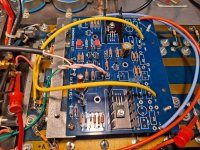
I mounted the trimmer pots to the back side of the board. I don't have the delicate kungfu trimmer pot turning abilities that Master Pass harnesses... So I used side adjust multi-turn straight pin trimmers. I drilled a hole in the center of the two outer pins and soldered the middle pin to an outer noting the trace. This allows you to flip the pots one direction or the other so you can use a long screw driver to adjust from the top if the amp with the cover off.
I put a heatsink on Q5 as it got hot. Q6 and Q7 got pretty warm but not hot. I would like to source the heatsinks that are in the original post
Initial Issues to resolve:
1) I cannot get the bias low enough. I was wondering if I should raise the value of R19 to maybe ~500 ohms or change out to a 1k pot. The old front end used to start with a higher bias that would lower as the amp came to temp. With the new, the bias raises as the temperature goes up... Bias used to settle around 60-80mv accross a 1 ohm source resistor. With the new front end, with the pot at its highest resistance, I got up to 54 degrees and 125mv and rising. I bypassed the thermostat for now. I will hook it up. Not excited to drill holes in the chassis but it's a good safety measure.
2) Also, the offset isn't bad but the pot only get's it down to 40mv. I am wondering if I need to refine the matching on Q3 and Q4. or change a resistor value. I used a cheapie transistor checker as I couldn't find a way to match like you can a JFET (using Mr. Pass's perscribed method). LSK170's are from the DIYstore and on my little transistor checker, they match perfectly as to be expected. Is there anything else that should be matched on the front end?
3) Square wave isn't very square. However, I don't have a signal generator. Can I expect a topping D90 to create an accurate square wave?
4) what are the heatsinks used in post 1?
On the S/500, and I assume other Threshold amps, the mounting studs for the front end board is a longer screw that goes through a output transistor case. I moved the long screw over one transistor. The boards that I used are the Nelson Pass boards with extra holes. None of the holes are meant to fit the S/500. I had to manually drill them and also make a bracket to adapt the other side of the board. See the picture. Everything is just mocked up until I get all of the details sorted. The channels was warmed up in the vertical position raised off of the desk about an inch. First pic was just a smoke test.
I mounted the trimmer pots to the back side of the board. I don't have the delicate kungfu trimmer pot turning abilities that Master Pass harnesses... So I used side adjust multi-turn straight pin trimmers. I drilled a hole in the center of the two outer pins and soldered the middle pin to an outer noting the trace. This allows you to flip the pots one direction or the other so you can use a long screw driver to adjust from the top if the amp with the cover off.
I put a heatsink on Q5 as it got hot. Q6 and Q7 got pretty warm but not hot. I would like to source the heatsinks that are in the original post
Initial Issues to resolve:
1) I cannot get the bias low enough. I was wondering if I should raise the value of R19 to maybe ~500 ohms or change out to a 1k pot. The old front end used to start with a higher bias that would lower as the amp came to temp. With the new, the bias raises as the temperature goes up... Bias used to settle around 60-80mv accross a 1 ohm source resistor. With the new front end, with the pot at its highest resistance, I got up to 54 degrees and 125mv and rising. I bypassed the thermostat for now. I will hook it up. Not excited to drill holes in the chassis but it's a good safety measure.
2) Also, the offset isn't bad but the pot only get's it down to 40mv. I am wondering if I need to refine the matching on Q3 and Q4. or change a resistor value. I used a cheapie transistor checker as I couldn't find a way to match like you can a JFET (using Mr. Pass's perscribed method). LSK170's are from the DIYstore and on my little transistor checker, they match perfectly as to be expected. Is there anything else that should be matched on the front end?
3) Square wave isn't very square. However, I don't have a signal generator. Can I expect a topping D90 to create an accurate square wave?
4) what are the heatsinks used in post 1?
Attachments

I installed a a 500ohm resistor at R19 and a 221ohm at R5. That seems to have solved the offset and Bias adjustability issues quite nicely.
I have the amp sitting in my shop (28 degrees celsius) with the amp running at about 50 degrees and 48mv bias. It sounds pretty good. I am excited to get both channels together and see what it can really do. The drivers on the front end are sitting about 55 degrees so that can come down a little bit. I will find better heatsinks. In the chassis, the temp would be higher.
I will go ahead and put the other channel together.
I am wondering if a lower value thermistor would better for initial bias. My amp is a class A/B with a relatively high voltage which equates to low current across the 1 ohm source resistors. Maybe decrease the thermistor to 1.5k and increase the bias on P2? I don't know if I would have to change the value of R17 or R18. I need to do another cold start to be sure.
optimize NTCs once when you have both channels done, heating same box volume
in any case, when you're done with second channel, just buzz
in any case, when you're done with second channel, just buzz
Thank you. I appreciate you taking the time to help.
The only holdback for for putting it all into the case is finding a heatsink that will cool the outputs but still fit between the front end and the output board. I have a couple of Macgyver type ideas that I'm going to try.
The only holdback for for putting it all into the case is finding a heatsink that will cool the outputs but still fit between the front end and the output board. I have a couple of Macgyver type ideas that I'm going to try.
Zen Mod,
I thought about this
"think
[Hz,F,Ohm]"
I was calculating in Farads, not uF. Hence the decimal point.
------
Okay, so I put the amp together and did some testing.
1) Cold bias starts at around 10mv-15mv and sits there. I had to put a heat gun on the heatsink outside of where the thermistor is to jump start the transistors. The bias is pretty sensitive too. Swings quite a bit when the AC comes on and moves the air around What is the reason for the thermistor? On the old front end with the optical bias, cold bias was somewhere around 90-100 and came down. With this setup, as the temperature rises, the bias goes up. So if for some reason, say the AC fails and the amp is left alone, it can overheat. I suppose the Thermal switch takes care of that. Would it make sense to use solely the pot for bias control and hook up the thermal switch? Or maybe use a PTC device for bias control? These are questions for my own learning.
2) Also, volume knob has to be pretty higher than before. I am wondering if I need to lower the value of R1. Maybe to something around 9k or 8k
3) I need to get or make a good square wave generator so I can test for ringing.
I reattached the schematic for convenience. I also edited it to account for the change on R29 to 9.8k.
---------------
I have a couple of functional tweaks that I have to do to it.
-The offset pots hit the power supply caps. On one side I can move the pot to the inside, other I will have to get creative. Maybe silicone it to the board and extend the leads into the pot.
-Maybe reroute or use longer power supply leads to get them away front the front end board. Run them between the caps rather than next to teh front end. Mostly to make it easier to get to the adjustment pots.
I will try to do a bit of a final write up and BOM in case anyone else wants to mod their S/500. So far, the amp sounds incredibly detailed. It is hard to go off of memory but I am noticing things I didn't before. Mostly in the high frequencies.
The last thing that I may want to try is to maybe purchase a lower voltage transformer and bias the amp more into class A, less A/B. I believe this one has two 152 volt secondaries that are center tapped to 76 volts. So it is sort of a dual mono. Two caps for each board, one cap for each rail.
all questions regarding amp function - need to be frimly addressed to Mithrandir itself
Mighty ZM didn't built one, and playing with these weeny shallow A Class amps is not exactly my fave area
I mean - anything above 15W/channel is already way over my head
volume - well, gain difference , what else
temperature - set Iq in temp equilibrium, what else; NTC needs some temperature rise to function at all, and that need to happen in contained thermal volume - meaning amp case closed
till now, we didn't saw any pic of your build as whole package, so no possible comments about your thermal management
Okay, I will post pictures later today. It is a stock Threshold s/500 but with these front end boards following the above schematic. Yes, temp was set in equalibrium to 52 degrees. Started it the next day and the initial bias was too low to start the transistors.
Last edited:
if you want tip-top function of NTC, extend its leads and mount it somewhere in central area of heatsink, in thermal contact with
hey, go wild, use some thermal goo
🙂
edit : on second look, it seems you already did that
hey, go wild, use some thermal goo
🙂
edit : on second look, it seems you already did that
Yep, there is a hole in the heatsink where the old ntc was, I put it in there with the wires. Thermal goop too
just do everything with patience, thermal equilibrium is major thing to achieve
only then you'll trace nature of the beast
I would help you with specifics but, as I said - I didn't built one, nor I will
most likely will use FE only for some small shenanigans, but not entire amp
only then you'll trace nature of the beast
I would help you with specifics but, as I said - I didn't built one, nor I will
most likely will use FE only for some small shenanigans, but not entire amp
Okay, thank you. I appreciate all of the help you have given me regardless. I plan to build one of your babblefish amps down the road. I am sure I will haunt you with a few questions then 😉
I seem to remember a hole in the heat sink that contained the thermal switch and the thermistors were on the stasis transistor case.
BTW. I have a few of the thermal switches from the original SA/1 left over from my repair days. If anyone needs one or a couple let me know.
BTW. I have a few of the thermal switches from the original SA/1 left over from my repair days. If anyone needs one or a couple let me know.
Yes, there are two holes and two components coming off of the original board that go into them. One being the thermistor. I didn't realize that the other was may be a thermal switch.
I could use a couple. That would be a good solution for me as I would have to otherwise drill holes into a heatsink. I will send you a message.
I could use a couple. That would be a good solution for me as I would have to otherwise drill holes into a heatsink. I will send you a message.
So those thermal switches, I thought, I had turned out to be PTC thermistors. oh well.
Now the same conundrum is afflicting me. I had previously rebuilt my SA/1 with bigger power supply and heatsinks, and increased the bias. They sound great and I am on the fence about changing out the front end board. The new front end board is simpler, few parts, so should be good (I always like simpler circuits) but the originally front end is extremely stable.
So while being on the fence I have laid out a new PCB using the schematic. It stands the drivers up so can fit small heatsink like the original and it saves board space, which is important as I can shrink it to 4"x4" which means the board house I use can make 10 boards for $5, plus $30 shipping., if you increase the size over that 4"x4" the price jumps $30. While I don't mind paying for good boards if it is necessary to make the board larger, in this case 4"x4" so more than enough space. And the smaller size will fit the four long screws on the original design with small L-brackets.
So I will finish the layout and maybe that will push me over the fence. 🙂
Zen, I think the issue is it would take a lot of macgyvering to make them work with the bolt patten that exists. I really like your FE. If I were building from scratch, I would have much rather had gone that route.
--------
John, could you use the oversized gerbers and make holes where needed? Minus the cascode section of course. Maybe move a couple of components on the board around for the hole locations? Also, for C2, if you want to use a nice cap like Silmics, the holes for the lead spacing will not work for 220uf sized caps. I used 10uf. I feel as though the amp lacks a little bass compared to before so I don't know if there was any reason Mr Pass settled on 220uf. I ordere some 47uf, 100uf, and 220uf silmics to try out.
On my boards, I needed the space for larger heatsinks. Especially since the top of my boards face into the heatsinks (only about 1" of space). My voltage is pretty high but the drivers sit at about 52 degrees as is...
I believe these are the exact heatsinks that Mr. Pass used. They fit perfectly in regards to the silkscreen on the PCB. They also move a decent amount of heat. I may just order a bunch on my next order just to keep them in the drawer.
https://www.mouser.com/ProductDetail/532-551002B00G
A thought, I don't know if this is possible, the offset pot is all the way to the side of the board. On one channel, it is super easy to get to. On the other channel, it is all the way at the bottom of the amp. I drilled holes in between the two outer holes so I could use straight pin side adjust pots that way I could flip them either way. The bias pot is relatively easy. On the original boards, the pots faced the rear which was pretty convenient.
Hi Zen Mod, I don't know what size your FE boards were. The one Nelson laid out was 3.5"x5.5", which put it in the $65 with shipping for 10 pieces.
Hi Mike, I don't think I can change the gerbers from another package though I have never tried to import them (maybe I will have to look into that), I just use the schematic capture and PCB layout program to make new boards. On the new board I am making, it fits between the current long screws which are on a 2.75"x 4.25" pattern. I laid out the PCB to use the 220uf Silmics for C2 and C3. Also I like to use multiturn pots that can be had with the screw on the top or on the side, and you can reverse them, so they can face up or down, and I always try to put them near the edge of the board so easier to adjust, and if possible make a location on both edges so you populate whichever one you want up. I design stuff from the point of easier to service if I can. Too many times working on my car I wanted the Toyota engineers throat in my hands. 🙂
Hi Mike, I don't think I can change the gerbers from another package though I have never tried to import them (maybe I will have to look into that), I just use the schematic capture and PCB layout program to make new boards. On the new board I am making, it fits between the current long screws which are on a 2.75"x 4.25" pattern. I laid out the PCB to use the 220uf Silmics for C2 and C3. Also I like to use multiturn pots that can be had with the screw on the top or on the side, and you can reverse them, so they can face up or down, and I always try to put them near the edge of the board so easier to adjust, and if possible make a location on both edges so you populate whichever one you want up. I design stuff from the point of easier to service if I can. Too many times working on my car I wanted the Toyota engineers throat in my hands. 🙂
Boyz will chime in and say in which post is complete info and board files, PassWorks by ZM

- Home
- Amplifiers
- Pass Labs
- New Stasis front end