as everything Papa publishes here, it's for use ...... but personal useWhen I make my own PCBs for this and other projects in the threads, I wonder if there are any written/unwritten etiqutte concerning honoring the origin of the design? I suppose I don't put the designers name on it, as they havent't approved my layout... Sure you all know this, but I don't - yet! (And, yes, I am having them produced i China.) Thank for any help!
🙂 morten
feel free to do your own pcbs, put Model and name Papa as Oracle ....... and that's it
if you're doing it commercially, that's another context

Thanks!as everything Papa publishes here, it's for use ...... but personal use
feel free to do your own pcbs, put Model and name Papa as Oracle ....... and that's it
if you're doing it commercially, that's another context
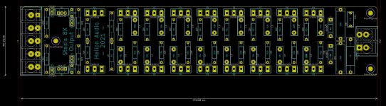
My first batch has already arrived, unfortunately without "Pass" on them.
(Only some model name. Misdeeds enclosed...)
But in the future there will be!
Attachments

And what a fine bit of work you did ZM; Pa, who's he? 🙂Blame (Lazy) Pa
He (again) pushed me to do all his work
So someone sent me a link to this thread and it's looking like the right one. Basically I have about 150-200 pairs of TO3 metal can outputs that I would like to use to build 50-100W/ch Class A. MJ15024/25s. More than enough. It looks like though that after reading about 15 pages in everyone is trying to go with a TO3P version. Is there any OS boards available to mount TO3s to? If not could the board that has been designed for the plastic version still be utilized. just using wires to connect from board to the metal versions. If you keep them short as possible. Also not being very familiar with Threshold is the Sa models a high bias Class A? It's not a "sliding type" bias correct?
thanks for any help.
thanks for any help.
existing OS pcb can be used with short wires ...... but - frankly - it is better just to be creative making buss- lines with 1.2 to 1.5mm Dia copper solid core
use few isolating standoffs with solder lugs, and it'll end as much neater arrangement than existing pcb on top of TO3s
Class A bias - as much you want and can in chosen cases, no sliders here
use few isolating standoffs with solder lugs, and it'll end as much neater arrangement than existing pcb on top of TO3s
Class A bias - as much you want and can in chosen cases, no sliders here
Zen Mods advice is spot on, follow that and you will be fine. These amps always look better with the TO3 metal cans all lined up in a row on the HS.
So to make sure I understand you correctly do not use any OS board at all. make all connections with bus wire running length of TO3s. What do you do with your emitter resistors? How to mount? As far as TO3s its ok to mount to aluminum angle and then angle to HS with thermal paste??
make separate copper wire bus, soldered to lugs on stand-offs
solder one end of resistors to bus, other end to each emiter
how to mount?
if you have Fetish for darn TO3, you ought to know how to mount them
several ways to do this, all of them involving drilling and most likely tapping, some of ways even involving milling
if you have transistors, know-how, tools, parts ........ use TO3
if you're not having just one of numbered, sell them, buy modern transistors
The + and - DC rails can be a bus to the collectors all in parallel with a wire from these back to the pcb (or the PSU direct) The base connections for the transistors can be a bus fed from the emitter of the 1st OP transistor, base of the 1st transistor is a wire back to the pcb. Then wire a short flying lead from each emitter back to the pcb to pick up each emitter resistor. Or you can hard wire it all on the underside of the HS angle bracket with insulated standoffs for one end of the emitter resistors. Your angle mounting approach is fine back to the vertical heat sinks - use plenty of decent sized screws (M5 or similar to attach to the HS)
Know I understand how to mount the TO3s was asking about the emitter resistors. But I get it they'll be soldered in place. Could even go for the to220 style resistors on the heatsink. So why dos this design use such high value emitters res. anyway? If the to3s are closely matched, could you get away with lower value resistors.
If i use the MJ15024/25 bc I have alot of them from same production run, will that compromise the overall design?
Use values as per Nelson's original Threshold design. Those MJ's will be fine. Also using TO220 resistors on heatsink will be a lot more drilling and tapping, and dont really lend themselves for point to point hard wiring.
Hey Freecrowder,
If you want to do TO3s then use a PCB and aluminum plate to do it right. There are gerbers and CAD for the TO3s. See Posts 1126-1135.
If you want to do TO3s then use a PCB and aluminum plate to do it right. There are gerbers and CAD for the TO3s. See Posts 1126-1135.

And Gerbers are back on post #1114.
And to answer your question, The SA/1-3 is Class A and you can run as much bias as your power supply and heatsinks can handle. I beefed up the power supply and the heat sinks and run about 8 amps of current through the 40 outputs and reach 55 C after about 30 minutes of warmup. But it sounds AWESOME.
And to answer your question, The SA/1-3 is Class A and you can run as much bias as your power supply and heatsinks can handle. I beefed up the power supply and the heat sinks and run about 8 amps of current through the 40 outputs and reach 55 C after about 30 minutes of warmup. But it sounds AWESOME.
Last edited:
Ok thanks for the info guys. So John do you have any pics? Is yours somewhere around 120W/Ch? I'm assuming stereo. Also assuming 20 pairs T03 per side. Does one T03 drive that many outputs per rail (10)? what supply voltage are you using.
Ok John I have found all your work in post. Thanks for all the work. As far as gerbers and having boards made is that ok to do? This is for personal use only.
what is the difference between NP FE and ZM FE? I can use either one with TO3 output.
what is the difference between NP FE and ZM FE? I can use either one with TO3 output.
The pics are in the posts listed above. The SA/1 is rated at 180 watts into 8 ohms, 300 watts into 4 ohms.
The gerbers are for your personal use. I don't think there is any difference from the front end board Nelson Pass created and ZenMod other than the wiring connection from FE to OP. ZenMod can correct me if I misunderstood the difference.
The Front End Drivers drive 2 stasis Transistors on EACH SA/1 OP board, one N and one P device (see schematic) and they drive the 18 current Mirror transistors, each board, on the rest of the board.
For my rebuilt copy of the frankenthreshold I upped the bias 60% so I runs deep into Class A. More heat, more power consumed, More Sound Quality.
- Home
- Amplifiers
- Pass Labs
- New Stasis front end