purrrfect
210mA, 6deep, rails 35Vdc
that sums in 85-90W of heat per side
deeeep A Class, aroundish 60Wrms@8R load
and I bet it would sing schweeeeet
210mA, 6deep, rails 35Vdc
that sums in 85-90W of heat per side
deeeep A Class, aroundish 60Wrms@8R load
and I bet it would sing schweeeeet
I just need to figure out a couple of led power meters now for the front panel 🙂
I calculated at about 88W of heat per side too. I just couldn't figure out the output power, other than it being less then the radiated power.
I'm giving it a four (ish) hour soak test this morning as a final check before its elevation to the loft so it can get its teeth into some speakers.
It has been a strange build really. I've never encountered so many little, fiddly problems and never so many layout changes, three in total. I even had to respray the back panel as it became so scratched whilst drilling it - I've never managed to do that before. It's like the amp didn't want to be built.
However I'm a big fan of vertically mounting toroidal transformers. It frees up so much space. I did the same for the KSA50 clone I built in an Apple Mac case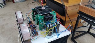
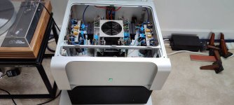


Folks,
I’ve been working on wiring but I have to admit that I’ve been trying to satisfy my OCD instead of electronics fundamentals which well I don’t know much about it.
I have placed negative DC voltages in one side and the positive in the other side, I’m hoping that in places that audio signals cross voltage signals it will be in a cross +, apart from that is all OCD design and layout.
I will lay all grounds tight to the bottom panel.
With that being said and before I spend more hours doing this, is there anything fundamentally wrong with what I’m doing??
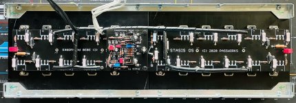
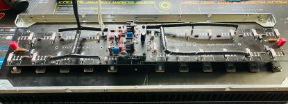
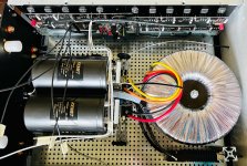
Cheers!!!
Alex
I’ve been working on wiring but I have to admit that I’ve been trying to satisfy my OCD instead of electronics fundamentals which well I don’t know much about it.
I have placed negative DC voltages in one side and the positive in the other side, I’m hoping that in places that audio signals cross voltage signals it will be in a cross +, apart from that is all OCD design and layout.
I will lay all grounds tight to the bottom panel.
With that being said and before I spend more hours doing this, is there anything fundamentally wrong with what I’m doing??


Cheers!!!
Alex
Last edited:
Looks great...much nearer than I could ever make.
Where did you get the capacitor mounts from, they are very smart.
I would lightly twist the secondary cables coming off the transformer. Have you figured out where to take the speaker -ive connections, it looks a bit cramped on the lower cap pair.
Where did you get the capacitor mounts from, they are very smart.
I would lightly twist the secondary cables coming off the transformer. Have you figured out where to take the speaker -ive connections, it looks a bit cramped on the lower cap pair.
looks beautiful
Than You!!
Looks great...much nearer than I could ever make.
Where did you get the capacitor mounts from, they are very smart.
I would lightly twist the secondary cables coming off the transformer. Have you figured out where to take the speaker -ive connections, it looks a bit cramped on the lower cap pair.
Thank You!!
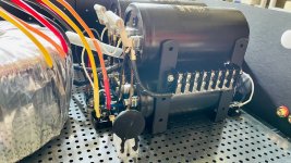
The Capacitor Mounts are nothing but some generic L Brackets I got from Amazon and some creativity 😉 Here they are...
Good advice on the Secondary Windings, thanks!
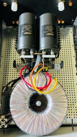
I'm thinking to connect the Speaker's -ive to the Ground Star, do you see that in this new picture?, one question about that, Is it OK to connect that directly to the chassis and mains ground?
I will put some NTC Thermistors between that star and the other connections to ground from FE and OS but how's the best way to accomplish all grounding, is it best to put everything thru that NTC?
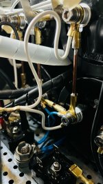
Last edited:
@AlexRivera,
please don't use the plastic things for the NTCs better use some made from bakelit or so (they goes hot).
please don't use the plastic things for the NTCs better use some made from bakelit or so (they goes hot).
@AlexRivera,
please don't use the plastic things for the NTCs better use some made from bakelit or so (they goes hot).
That's a very good point, I checked what I'm using and the NTC between mains and the Toroidal primaries is connected to a Terminal Block made of
Polyamide (PA66), Nylon 6/6 which theoretically has a melting point of 515.9°F (268.8°C) then the other NTCs between the Bridge Rectifiers and the filtering capacitors are connected to those "Plastic" Terminal Strips which are made of Polybutylene Terephthalate (PBT) with a Melting point of 433.4°F (223°C).
The NTC's body temperature @ Max Current is 215°C so yeah its close to the terminals melting point, the NTC's max steady current is 40A so I doubt it will ever get there but is still something to consider.
Now I have searched for bakelite terminals and only sketchy vendors have them, when I search for bakelite terminals in the reputable sites the results that come back are not really bakelite but the same type of materials I'm already using, do you know about a source for these?
why you put those NTCs between bridges and caps?
value?
Hey ZM, I asked for help to Anatherm engineers since I couldn't found any documented help with a donut this big and this is what they suggested...
Recommendation:
Transformer primary:
We recommend Ametherm part number MS35 1R040.
Install one(1) MS35 1R040 in series between line power and primary lead of toroidal transformer.
Capacitor bus:
We recommend Ametherm part number MS35 1R040.
Install one(1) MS35 1R040 in series between diode bridge and capacitance.
Given: (as provided by customer)
(a) 2.5kVA toroidal transformer
(b) 250,000µF capacitance on 70VDC secondaries
(c) Mains voltage = 120VAC 60Hz single-phase primary
Our Assumptions:
(a) Inrush current for toroidal transformer = 100x steady state current
(b) Peak V = (Vrms)(1.414)
(c) Maximum allowable inrush current on transformer primary = 10x 15A D breaker rating
(d) Maximum allowable inrush current on capacitor bus = 2x bus current
Our Calculations:
Peak voltage = (120VAC)(1.414) = 169.68V
Rated maximum steady state current of transformer = 2500VA/120VAC = 20.83A
Rated maximum bus current = 2500kVA/70VDC = 35.71A
Inrush current = (100)(20.83A) = 2083.3A
Inductive impedance Xl = peak voltage / inrush current
= 169.68V/2083.3A = 0.0814Ω
Inductance in henries L = Xl / 2∏f
= 0.0814Ω/376.99H = 0.000216H
(Transformer) Energy in joules thermistor needs to handle without self-destruction =
= (0.5)(L)(I2) = (0.5)(0.000216H)(2083.3A2) = 468.7J
(Capacitance) Energy in joules thermistor needs to handle without self-destruction =
= (0.5)(F)(V2) = (0.5)(0.25F)(70.0V2) = 612.5J
(Transformer) Minimum zero-power resistance
= peak voltage / maximum allowable inrush current
= 169.68V/150.0A = 1.13Ω
(Capacitor) Minimum zero-power resistance
= peak voltage / maximum allowable inrush current
= 70.0V/71.42A = 0.99Ω
Selection Criteria:
We have established the minimum characteristics required of the inrush current limiter:
(a) Minimum zero power resistance of transformer thermistor = 1 ohm
Minimum zero power resistance of Capacitor thermistor = 1 ohm
(b) Energy of transformer inrush current limiter = 468 joules
Energy of capacitor inrush current limiter = 613 joules
(c) Steady state current transformer primary = 21 amp
Steady state current capacitor bus = 36 amp
The only place I have put a NTC is between the star gnd of the PSUs and the incoming mains earth (chassis).
Gosh, this A class amp stuff is just learn, learn, learn....
Turned the amp on last night and no sound from one channel...bugger...plugged in the Krell and pondered the joy of transistor testing the Stasis.
Plucked up the courage this afternoon the open the top. Disconnected the silent channel from the PSU and checked continuity between the silent board's rails and gnd, nothing, not short. Hmmmm. Double checked the transistor casing to the heatsink, no short.
With both channels disconnected from the PSU, powered up the PSU boards. Only one set of LEDs comes lights up on one board. "Really? PSU gone phutt?" Checked the output voltages on the silent channel's PSU board, nothing. Then I noticed the R5 resistor on the PSU providing some CRC filtering between the caps.
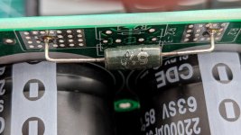
No idea why the picture is upside down...
Anyhoo, both 0.5R resistors on the silent channel are OC.
Then I remembered building the DIYAudio PSU PCB for my F5T and wondering why there were multiple resistors in parallel forming the R in the CRC cct.
As a double check I tried the working PSU board on the silent channel, and it is no longer silent - Phew!
Time to order more resistors, 3Ws and double/triple them up for better power handing.
A useful lesson today was learnt.
Turned the amp on last night and no sound from one channel...bugger...plugged in the Krell and pondered the joy of transistor testing the Stasis.
Plucked up the courage this afternoon the open the top. Disconnected the silent channel from the PSU and checked continuity between the silent board's rails and gnd, nothing, not short. Hmmmm. Double checked the transistor casing to the heatsink, no short.
With both channels disconnected from the PSU, powered up the PSU boards. Only one set of LEDs comes lights up on one board. "Really? PSU gone phutt?" Checked the output voltages on the silent channel's PSU board, nothing. Then I noticed the R5 resistor on the PSU providing some CRC filtering between the caps.

No idea why the picture is upside down...
Anyhoo, both 0.5R resistors on the silent channel are OC.
Then I remembered building the DIYAudio PSU PCB for my F5T and wondering why there were multiple resistors in parallel forming the R in the CRC cct.
As a double check I tried the working PSU board on the silent channel, and it is no longer silent - Phew!
Time to order more resistors, 3Ws and double/triple them up for better power handing.
A useful lesson today was learnt.
Rails are at -/+35V.
I had noticed that the resistors where getting very hot, too hot to touch previously.
It should be only dissipating 1.5W.
I had noticed that the resistors where getting very hot, too hot to touch previously.
It should be only dissipating 1.5W.
in my CRC I'm using peasant 0R1/5W Wirewound
go figure
0R5 is too much there..... and size of these resistors is weeny
go figure
0R5 is too much there..... and size of these resistors is weeny
- Home
- Amplifiers
- Pass Labs
- New Stasis front end

