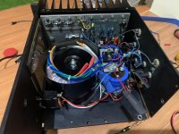
Built the boards, just waiting for the case to arrive... 🙂
Pix or it didn't happen 😀
you know stubborn me
no spades, strictly soldering

Will scratch that then, ordering right now!!

you know stubborn me
no spades, strictly soldering
ZM, I need to order some multi colored cooper wire for this project, you know for all the interconnects, etc. what gauge can the holes on the PCBs handle, 14, 16, 18?
In general what gauges does everybody use?
Tanks,
Alex

Please, can you remind me the gerbers post?
Please, can you remind me the gerbers post?
Page 29 - post 281 is the start.
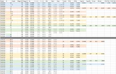
What’s a good tolerance for matching the output stage BJTs?
It's a compromise between what you want and what you get.
I bought a batch of 40 pulls (used) from Ali and managed to get 3.5 sets of 2 x (1 driver + 3 outputs), with a Vbe match < 1.5% and a Hfe match < 5%. The .5 set (light blue) is because I ran out of suitable driver, so, the Hfe match is off; the Vbe match is still good though. Anyway, 2 sets is all I need.
Interesting to note: in the world of semiconductors, sexual equality doesn't exist, and the PNP's/P-channel's always perform better. 🙂
Attachments

It's a compromise between what you want and what you get.
I bought a batch of 40 pulls (used) from Ali and managed to get 3.5 sets of 2 x (1 driver + 3 outputs), with a Vbe match < 1.5% and a Hfe match < 5%. The .5 set (light blue) is because I ran out of suitable driver, so, the Hfe match is off; the Vbe match is still good though. Anyway, 2 sets is all I need.
Interesting to note: in the world of semiconductors, sexual equality doesn't exist, and the PNP's/P-channel's always perform better. 🙂
Ah I see. I was looking at 1% tolerance on the Vbe and 10% on the Hfe so I’ll tighten up the Hfe tolerance. Thank you
making welder.......... or having Apogees?
Hahahaha, almost!!!
I’m going all in, 12 pairs per channel 😉

i am planning to use a 910va transformer (+/-57vdc after rectifier/C filter). would it be enough to power 5 x 100w channels if bias is kept on the conservative side for stable low impedance load?
is this a reasonable pi topology for the rails regulation?

is this a reasonable pi topology for the rails regulation?
- Home
- Amplifiers
- Pass Labs
- New Stasis front end