if you're intending to finish this, wisest thing is to open dedicated thread**
that way this one will be less cluttered, and you'll have consistency in your own
older I am, harder pingponging is; sometimes I'm able and willing to help, but just following trail of information is too messy and confusing
**prepare all relevant schematics and post them at start; pics of Haf inside can help too
has anyone built a complete one yet? I have two 40v 1kva traffos lying around, sufficient or more voltage required?
Two 40V windings in series will give you about 170-180W @ 8R.
Whether that equates to "sufficient" depends on you.
Whether that equates to "sufficient" depends on you.
Folks, everyone talks about Idss matching for the 2SK170, but if you had a curve tracer what would you be looking for?
Perhaps Vgs-Id, something else?
Perhaps Vgs-Id, something else?
My experience with the Toshiba parts is that they have great consistency.
If you have same Idss out of same box, then they are functionally identical.
If you have same Idss out of same box, then they are functionally identical.
same curves

My experience with the Toshiba parts is that they have great consistency.
If you have same Idss out of same box, then they are functionally identical.
Thank You!!
I'll play around and see what I find 😉
My experience with the Toshiba parts is that they have great consistency.
If you have same Idss out of same box, then they are functionally identical.
Confirmed, I matched a few within .1mA then ran them in the Curve Tracer and they pretty much create the same curves.
The thing is, and I may be wrong, I expected them to all have 1 V across the 100ohm resistor but most of the are around the .85 area, followed by .95 then a few in the .70 range, not that easy to match these little ones....
BTW I'm using 12V at the Drain.
There is a range of Idss for the parts. Assuming you are using 2sk170BL,
anything from 6mA to 12mA (0.6 to 1.2V in your test) is possible.
The parts I have go from about 6.5mA to a bit over 10mA.
anything from 6mA to 12mA (0.6 to 1.2V in your test) is possible.
The parts I have go from about 6.5mA to a bit over 10mA.
There is a range of Idss for the parts. Assuming you are using 2sk170BL,
anything from 6mA to 12mA (0.6 to 1.2V in your test) is possible.
The parts I have go from about 6.5mA to a bit over 10mA.
Yes, I'm using 2SK170BL, thanks for the heads up!
I've told ya before - even 2SK170GR will do the job, or appropriate LSK group (A, by fuzzy memory)
Iq of LTP is between 4 and 5mA (depends of actual Vbe of Q5 and D1,D2) , meaning half of that per JFet
so, even eenyweeny are OK
Papa is making Sissy amps lately
Iq of LTP is between 4 and 5mA (depends of actual Vbe of Q5 and D1,D2) , meaning half of that per JFet
so, even eenyweeny are OK
Papa is making Sissy amps lately
Has anyone completed one of these amps yet and have a parts list used for the power supply and driver boards (transistor models)?
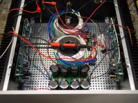
As just mentioned, I'm in the process of setting the bias and have a question. I'm attempting to set bias so I get about 50 degrees C on the heatsinks. I've been monitoring the current across R13 on both channels. One is running about 190 mA and the other about 110mA. Interestingly (to me at least) the channel with lower current is running a bit hotter. What's more important: matching bias on each channel or heatsink temp? DC offset staying around 30mV on each channel.
And, just to prove I'm close, I'm attaching a photo.
And, just to prove I'm close, I'm attaching a photo.
Attachments
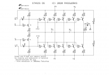
R13??
ref. to which (damn!) schematic?
btw. if you did mechanical assembly (thermal interfaces in first place) then temperatures would comply with electrical values, in both channels
ref. to which (damn!) schematic?
btw. if you did mechanical assembly (thermal interfaces in first place) then temperatures would comply with electrical values, in both channels
Your 6-deep output section. Schematic attached.
I am disappointed that you can't read my mind - maybe the distance is too great or my mind to empty...
And now that I'm looking at it again, I suspect it doesn't make sense to measure the current across that resistor. But I will appreciate any explanation as I'm still learning.
Cheers.
I am disappointed that you can't read my mind - maybe the distance is too great or my mind to empty...
And now that I'm looking at it again, I suspect it doesn't make sense to measure the current across that resistor. But I will appreciate any explanation as I'm still learning.
Cheers.
Attachments
Last edited:
good then 🙂
as I said - if you did everything by the book, have matched buggers in OS, then thermal and electrical data must be similar between channels
though, old and unreliable as I am, I did bought contact temp.meter ( DMM with thermal probe) , just to get more precision in pinpointing some problems I had
by precision , I mean - with IR gun thingie you're precise enough in reading, but always unsure if you need point or small area
(Papa's palm technique and figures - always valuable as rule, and totally reliable enough when everything goes well)
when in doubt, doubt everything - check voltages at all emiter resistors, just to be sure that everything is uniform , as it is meant to be
and yes - by Treshold papers - temperature is main guide, while electrical data is to be observed as confirmation that everything behaves
Check the voltage drop on all 10 emitter resistors, to see if 1) the resistors are all in spec and 2) the output transistors are all OK and in spec as well. I would not have thought you would see that big a current bias difference between channels with the heatsinks at the same temp. What rail voltage are you running?
- Home
- Amplifiers
- Pass Labs
- New Stasis front end