I particularly like the sentence in the attached manual which reads: "Assembly and final adjustment is completed under the supervision of Nelson Pass, originator of the Stasis circuit and co-founder of Threshold"
So maybe if Nelson reads your post, he might be able to shed some light on your question.
That is the hope. This thread is quite interesting and informative. The pcb posted in #1 could be used as a preamp or a headphone amp. Just short the bias spreader.
Last edited:
Just re-read whole thread once again. Great job!
Would also be very interested in duplicating Threshold SA1 monoblocks with new FE.
I have Thiel CS6 that are very amper hungry. I’m not afraid of huge heatsinks, large toroids and many output pairs. Just would like to make it once and good 🙂🙂🙂 preferable as mono amps. Any help how output stage would look and how many output devices to use?
Many Thanks!
Hi,
What is the max. voltage for the FE 😕
80V rails, 2pcbs of 8deep per channel (so 16 pairs per channel) , all solved
What is the max. voltage for the FE 😕
80V rails, 2pcbs of 8deep per channel (so 16 pairs per channel) , all solved
🙂
This is the way
Hi,
What is the max. voltage for the FE 😕
above 50V rails I would start changing ZTX 450/550 to something else
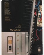
THRESHOLD's Excellence
Hello Zen Mod and all,
The renaissance of STASIS [R] in this thread is a testament to its 'foreverness'.
I attached a beautiful art picture to complement your schematic. It was shown in AUDIO November 1991.
Best
Anton
dunno which models, but details lies in these text parts:
"common point for parallel mono amps"
"output + binding post except inverting channel of bridged amps, in which case connection is made to - binding post"
"NOTE 2. ..................... and 1/2 of the complete output stage for mono amps"
conclusion - Lego blocks are here ....... you can combine 'till the end of time 🙂
fact - I'm utterly lost in Treshold models nomenclature ....... stopped even trying to figure it out
Hello Zen Mod and all,
The renaissance of STASIS [R] in this thread is a testament to its 'foreverness'.
I attached a beautiful art picture to complement your schematic. It was shown in AUDIO November 1991.
Best
Anton
Attachments
Am I correct in understanding one would need two output stages per channel when going SuSy?
Also, using 35-40V rails (19.1-22.6Vrms) into an 8-ohm load should result in about 45-64W output (if my math is correct). But how much heat will need to be dissipated?
Also, using 35-40V rails (19.1-22.6Vrms) into an 8-ohm load should result in about 45-64W output (if my math is correct). But how much heat will need to be dissipated?
of course - you need two OS pcbs when going SUSY, to have first and second to make bridge of them
with 40V rails, let's say round figure of 35V is what you get after losses at peak, so voltage envelope is 70Vpp
that's what you get from one half of bridge
other half of bridge is driven in opposite phase, you have another/once more 70V in opposite phase, so in bridge that's 140Vpp
140Vpp/2/1.41 gives you 49.5Vrms
as P= Vrms^2/Rload, that's 306W @ 8R
heat is in direct relation with how much of that you want to be in A Class, dictated by sheer size of your enclosure ( say 55C in Summer) and greenies you invest in PSU
for that , I wouldn't go with less than 99mF per rail ........ and nice 800VA Donut ....... speaking of one channel
though, do not forget that SUSY part of project isn't verified in vivo - most likely it needs some polishing, to get desired level of stability, mainly thinking of absolute and relative offsets
Mighty Moi is not going that route, too much on my plate already
Last edited:

of course - you need two OS pcbs when going SUSY, to have first and second to make bridge of them
with 40V rails, let's say round figure of 35V is what you get after losses at peak, so voltage envelope is 70Vpp
that's what you get from one half of bridge
other half of bridge is driven in opposite phase, you have another/once more 70V in opposite phase, so in bridge that's 140Vpp
140Vpp/2/1.41 gives you 49.5Vrms
as P= Vrms^2/Rload, that's 306W @ 8R
heat is in direct relation with how much of that you want to be in A Class, dictated by sheer size of your enclosure ( say 55C in Summer) and greenies you invest in PSU
for that , I wouldn't go with less than 99mF per rail ........ and nice 800VA Donut ....... speaking of one channel
though, do not forget that SUSY part of project isn't verified in vivo - most likely it needs some polishing, to get desired level of stability, mainly thinking of absolute and relative offsets
Mighty Moi is not going that route, too much on my plate already
Oh yes, I see where I stuffed up. Have to go with lower voltage rails then.
Thanks Zen Mod!
- Home
- Amplifiers
- Pass Labs
- New Stasis front end