No problem with that approach, of note is the fact that Mr Pass has not gone down that route in any of his designs over 40 years or more as far as I know. A beefy cap multiplier should work well, many others here have implemented it.
Blk Dynamite, 800VA is more than sufficient - with 45vAC sec you will have approx 60VDC rails and heaps of current available. You will need to use 80VDC rated caps and aim for 60,000uF per rail minimum for a stereo build. Or go dual mono with 2 off 400VA transformers. That will all fit nicely in the pico 500mm deep enclosure. I am looking at 100,000uF per DC rail, but only at 40VDC.
Nice! Gonna see if i can squeeze in a CLC supply like i did my F4. Also want to go 12 deep per side so it’ll be a little monster
Make sure the pass device(s) can take the steady state load... This is going to have a lot of bias current.
Will do
Hi,
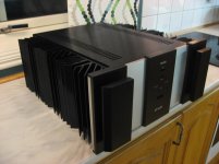
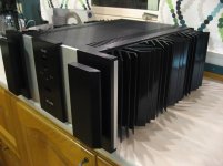
I will use this chassis for my Stasis amplifier:
It is a mix of a XA160 chassies with a Krell front.
(It has been lying here for a few years now, time to put it to use 😉 )
How far can I go, regarding heath dissapation ?
I mean, how many output devices, rail voltage etc.
I have ordered :
5 off ZM Stasis FE pcb's
5 off ZM Stasis SUSY FE pcb's
5 off ZM Stasis OS 8 deep pcb's to play with 😀
J.R
Attachments
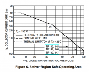
300 watts per channel, into a 4 ohm load, requires 12 amps of supply current per channel. If it comes from a capacitance multiplier, I recommend 2 pass transistors in parallel (with ballast resistors!) per channel. Now it's "only" 6 amps per pass transistor, which is well within the safe operating area of many high power devices that DIYers might select.
VCE = 3V , ICE = 6A
VCE = 3V , ICE = 6A
Attachments
So, if the amp's rails are 35V for a 50W per channel output each CapMx has about 1.5A through them. Say the Cap Mx is dropping 4V that's about 6W in the Cap Mx devices, 3W each. I can bolt them to the amps base plate, no need to a separate heatsink methinks.
I was looking at the measurements of the output stage pcbs and noticed that
if one plans to use them with USM heatsinks then there is about 20.5mm
horizontal distance between the mosfet mounting hole and the centre pin hole.
For those planning to use TO3P or TO247 parts, this works perfectly. I have
some MJL21193/21194 in the larger TO264 package and it looks like they can still work
if I bend the legs a bit backward instead of straight up for mounting onto the PCB.
Or perhaps this just means I should order some TO3P Sankens. 🙂
NP/ZM boards components
I'm in the process of ordering the elements to populate the boards. I will be assembling both the NP and the ZM. need advice regarding the following:
1. resistors will be type Dale RN55D?
2. Capacitors, Wima and Nichicon?
3. Transistor from the DIY store matched?
Any suggestion is greatly appreciated.
That will be tight for the devices in the TO264 package. I will be using Sanken TO3P's, I have a few candidates already.
If you are going to buy some have a look at these Sanken pairings:
2SA1294 / 2SC3263
2SA1695 / 2SC4468
2SA2223A / 2SC6145A or the lower Vceo 2SA2223 / 2SC6145
2SA2151A / 2SC6011A
All of the above are specifically designed for audio amp output stages and are used by a lot of the well known commercial manufacturers. They are all available at the usual distributors (Digikey and BDENT or Arrow Electronics) where they will all be genuine as well. Just a warning to all - beware, as a lot of these are listed by China based ebay sellers, all will most likely be 100% fakes no matter what their listing says.
As Zen Mod has mentioned earlier in this thread and with his test circuit - for Vbe. In testing I have done on Sanken devices, I find they are already very close for this measurement. For instance, out of 30 devices of each for my first mentioned pairing, the Vbe only had a spread of 5mV between 30. As ZM mentioned this is way better than required.
I'm in the process of ordering the elements to populate the boards. I will be assembling both the NP and the ZM. need advice regarding the following:
1. resistors will be type Dale RN55D?
2. Capacitors, Wima and Nichicon?
3. Transistor from the DIY store matched?
Any suggestion is greatly appreciated.
1. all resistor packages are regular 0207 size, in 10mm pitch between solder pads/bent pins; big ones are regular Panasonic/whatever MOX 3W size, which is 0617, 22mm pitch
2. take brand name ones and that's it
3. LSK170 of course will do ; in this case A Grade ones too
Were any of the Threshold amplifiers bridged or parallel output boards?
In particular, I am interested in the SA1. I do not see that SA1 mentioned in any of the schematics in post #1 of this thread.
In particular, I am interested in the SA1. I do not see that SA1 mentioned in any of the schematics in post #1 of this thread.
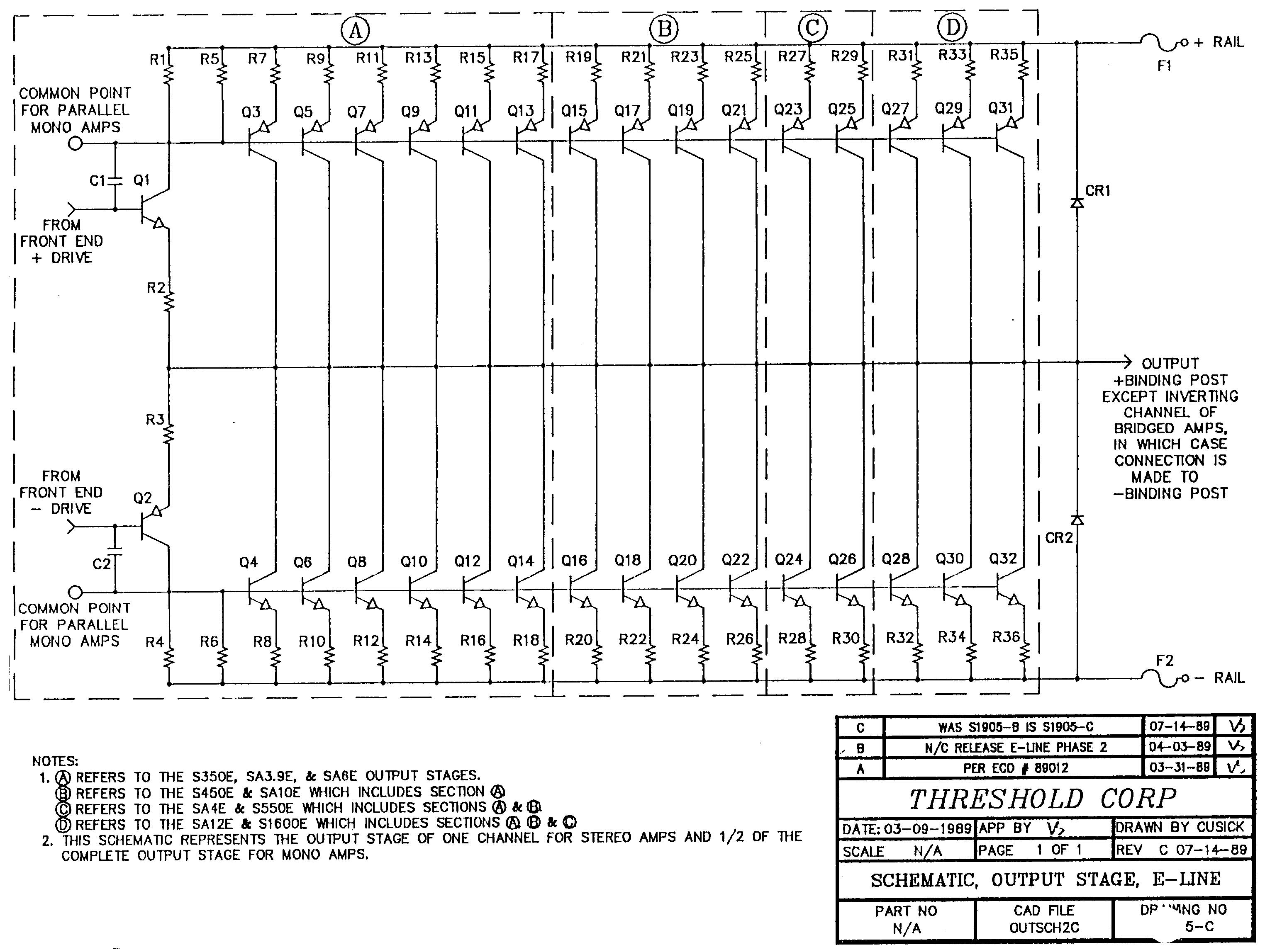
dunno which models, but details lies in these text parts:
"common point for parallel mono amps"
"output + binding post except inverting channel of bridged amps, in which case connection is made to - binding post"
"NOTE 2. ..................... and 1/2 of the complete output stage for mono amps"
conclusion - Lego blocks are here ....... you can combine 'till the end of time 🙂
fact - I'm utterly lost in Treshold models nomenclature ....... stopped even trying to figure it out
Page 14 and 15 of the attached PDF has output transistor counts for the various models.
A picture of the SA1 online shows only an RCA input jack on the rear panel.
My conclusion is that the monoblock amplifiers have parallel output boards connected to a common input PCB.
That is just a guess based on reading.
A picture of the SA1 online shows only an RCA input jack on the rear panel.
My conclusion is that the monoblock amplifiers have parallel output boards connected to a common input PCB.
That is just a guess based on reading.
Last edited:
So, possibly an SA1 is an S500 with the output boards in parallel to make a monobock. Maybe the voltage rails are different and maybe the bias setting is different.
Last edited:
I particularly like the sentence in the attached manual which reads: "Assembly and final adjustment is completed under the supervision of Nelson Pass, originator of the Stasis circuit and co-founder of Threshold"
So maybe if Nelson reads your post, he might be able to shed some light on your question.
So maybe if Nelson reads your post, he might be able to shed some light on your question.
- Home
- Amplifiers
- Pass Labs
- New Stasis front end