size 1206 SMD
whichever you get, they will be good
though, hold your horses, let's wait for Papa's verdict (values)
whichever you get, they will be good
though, hold your horses, let's wait for Papa's verdict (values)
Thanks again ZM, just gathering all info and definitely waiting on the masters blessing on this - this will be a great project to bring to life.
With such big available free space inside the chassis why use SMD capacitors ? 
Dosent trough hole film caps soldering more convinient for many Diyers without special SMD hot air station ?
Dosent trough hole film caps soldering more convinient for many Diyers without special SMD hot air station ?
Zen Mod, I have just looked at the UMS drilling pattern and all your output transistors as shown on your design match the UMS pattern for their mounting.
However I don't think the pcb mounting holes you have shown match the 80mm horizontal x 40mm vertical grid for the board mounting on the UMS pattern. Your grid for these looks like about 60mm vertical x 120mm or 80mm horizontal.
Can you check that thanks.
However I don't think the pcb mounting holes you have shown match the 80mm horizontal x 40mm vertical grid for the board mounting on the UMS pattern. Your grid for these looks like about 60mm vertical x 120mm or 80mm horizontal.
Can you check that thanks.
To make the output PCB as universal as possible, a compromise might be an 8 device (4 deep) PCB with two cut lines to make it a 6 device PCB; that way you could have a 12 deep (24 devices total) 300mm monoblock chassis or an 8 deep 400mm stereo chassis.
while I'm in the Office 🙂
let's avoid cutting
Attachments
-
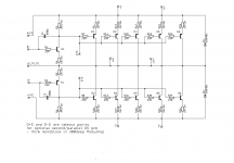 Stasis OS 6deep sch.png39.6 KB · Views: 761
 -
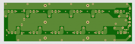
 Stasis OS 6deep Eagle bottom.png42.8 KB · Views: 752
 -
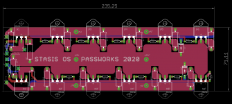 Stasis OS 6deep Eagle all.png46.1 KB · Views: 674
 -
 Stasis OS 6deep pcb render bottom.png72 KB · Views: 658
 -
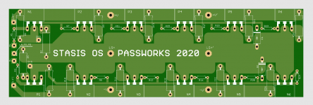 Stasis OS 6deep pcb render top.png112.5 KB · Views: 705
 -
Gerbers STASIS OS 6deep.zip31.4 KB · Views: 156

Total 4 caps.Soldering just 2 SMD caps per board is not too bad - can be done with normal iron.
8 more sensible joints than his through hole classic equivalent.
Yes can be done....but is easy clean and convenient soldering without hot air station
and special SMD soldering fluxes products etc. I have doubts..
Edit : Source power resistors are not miniature size anyways 😉
Zen Mod, I have just looked at the UMS drilling pattern and all your output transistors as shown on your design match the UMS pattern for their mounting.
However I don't think the pcb mounting holes you have shown match the 80mm horizontal x 40mm vertical grid for the board mounting on the UMS pattern. Your grid for these looks like about 60mm vertical x 120mm or 80mm horizontal.
Can you check that thanks.
no mounting holes on pcb, so no standoffs - 48 transistor pins are more than enough for 75gr pcb, same weight of resistors and several hanging wires
if PL amps can be made that way, no reason that this one can't be made in same fashion
Now I have woken up ZM, I mistook the LS, V+ and V- lands for mtg holes.
I like your second 6 pair layout, now everybody will be happy.
We wait on papa's seal of approval.
I like your second 6 pair layout, now everybody will be happy.
We wait on papa's seal of approval.
I guess one would put something under the PCB to support it while one
solders some pins. Should be reasonable to do.
solders some pins. Should be reasonable to do.
I guess one would put something under the PCB to support it while one
solders some pins. Should be reasonable to do.
like usual, Dennis is one with brain for practical details 🙂
yes, you're right - some temp supports are usual accessories - (matchbox, Fuyitsu relays, whatever), though - I'm finding eyeballing is often good enough at my workbench, especially when I have just one of wanted supports

Yeh, a couple of 6 to 10mm standoffs while one solders all the 90 deg bent transistor legs, would be just ideal.
As ZM says, if good enough for Nelson back 35 years or so ago, then it should be OK still today. When you think about it, 36 or 48 stout transistor legs will be strong.
As ZM says, if good enough for Nelson back 35 years or so ago, then it should be OK still today. When you think about it, 36 or 48 stout transistor legs will be strong.
ZM, now you have broken all records in getting 2 layouts done in a day - what are you going to do tomorrow? Have a rest I say, thanks again for your generosity.
Yeh, a couple of 6 to 10mm standoffs while one solders all the 90 deg bent transistor legs, would be just ideal.
As ZM says, if good enough for Nelson back 35 years or so ago, then it should be OK still today. When you think about it, 36 or 48 stout transistor legs will be strong.
dunno for how long , but current PL amps are made as that - wherever you see big bank of mosfets, pcb is without standoffs
OK, plethora of times confirmed that I'm blind, but I really didn't see them
ZM, now you have broken all records in getting 2 layouts done in a day - what are you going to do tomorrow? Have a rest I say, thanks again for your generosity.
that's trivial, and certainly not even near any record
what's not trivial is - numbers of pcbs made for prototypes - still not even put on workbench ........ also number of pcb files waiting to become pcbs.......also number of schmtcs waiting for any way of prototyping ......

A question for Nelson, I notice in your post #1, the photo shows you did not load the R22 / C6 zobel components as tested. Any comments as to why and should members have these components in place for their likely builds?
- Home
- Amplifiers
- Pass Labs
- New Stasis front end