You could have asked me you know. 😉 The driver is actually no different to any of the other MA units in its broad LF response characteristics; no LP shelving circuit needed for these. If it was, I would have provided it. Slapping shelving circuits on these things without reference to the power response causes an LF heavy balance (and not in a good way). Been there, done that; I've been working with the prototype driver here for a couple of months.
Last edited:
Can you clarify what you're asking, or saying? Sorry, it's 0310 here. The two drivers are measured under slightly different conditions, with the new unit also having a slightly different data presentation from Clio rather than the long-gone LMS, but as you can see, they share the same general axial characteristic, with the larger unit's power response being slightly narrower, as you'd expect.
Last edited:
In the 10.3 in the graph above, I see +3 to+5db @ 200-500hz compared to 800hz, then the response sneaks up then takes off past 6khz.
I think you could use this as an advantage.
Or the response above is not measured on an infinite baffle ? like a wall ?

I think you could use this as an advantage.
Or the response above is not measured on an infinite baffle ? like a wall ?
I don't see any driver bass bump in the frequency response.
If you look at the MA200 FR graph, there is a significant bump in the LF. Look at how the measured response compares to the calculated response - there's proababy about 6dB difference around 120 Hz. Mind you, I'm not sure of the full measurement conditions. (Also, it's tricky to read the graph because the vertical scale is quite compressed, nowhere near the IEC recommended 25dB per decade aspect ratio.)
For the moment, there's no MA200 available here in France.
I was ready for the Alpair 12P, but now I am hesitating for the new MA200 :


I would even be interested with a MA200-P... 😉
T
I was ready for the Alpair 12P, but now I am hesitating for the new MA200 :
I would even be interested with a MA200-P... 😉
T
Sorry for the slow response -still fighting the dreaded lurgy so been out of it since about 0330. Oh well, lots a whole lot (and then some) worse off, so can't complain.In the 10.3 in the graph above, I see +3 to+5db @ 200-500hz compared to 800hz, then the response sneaks up then takes off past 6khz.
Right, that's more or less the 'standard' MA axial response characteristic; to varying degrees most of the drivers have it, or a variation thereof, including MA200-M.
You can -pretty much every enclosure I've done for the MA units does, to different extents depending on what it's designed for / how it's intended to be used. The pensils & various horns are the 'obvious' examples, but I build it into all of themI think you could use this as an advantage.
MA drivers are measured on an IEC 268-5 equivalent baffle with the driver offset on a hybrid of golden and industrial acoustic ratios. Starting with MA200-M, 'we' (I say 'we' because the change was my doing, so in this case shooting the messenger is entirely fair 😉 ) have made a few tweaks to the protocol to better represent real world use: we've added in the mathematical IB curve derived from the published T/S data set, and the mic. position is shifted to 0.5m, with the levels normalised to the 1m/2.83v value to allow comparison across different coil impedances. That last was also something I've been requesting for some time. The closer mic. position reduces a little of the unwanted baffle artifacts -there are various ways & means around this, but this one was the most practical for the available facilities & staff time. FWIW, this is more or less the old measurement protocol Seas used to do up to about '03, when they shifted to small test boxes, albeit with that nearer mic. location & levels normalised. Further out, the LF response inherent to the driver can get a little exaggerated by the baffle load unless you tweak things a bit, so reducing this is useful.Or the response above is not measured on an infinite baffle ? like a wall ?
🤣
Last edited:
Scott, Is there any chance you can talk them in to publishing the charts at like 50db to 100db rather than 10db - 110db? 😉
It can do, but it depends on the design, so there's no single 'this is the limit' that applies equally to all conditions -what you can (to a point 😉 ) do with one type of load & usage doesn't necessarily carry over to another. As a very generalised point, if you get the rear baffle too close to the driver, you'll start to compression (mass) load it, and if that's non-linear, as it probably will be if not designed in, the behavior will change; at extremes, the air load can physically deform the cone.
Last edited:
Scott, I'm following this thread with great interest and I was wondering since you were/are a part of the development team behind new driver, can you share some preliminary listening/sonic impressions or maybe a comparison with some of the existing MA drivers ?
If I understand correctly, it could fit into Joan enclosure ? Does it mean it could also fit in one of the existing horns of the Megalith family, or a new family member is under development ?
If I understand correctly, it could fit into Joan enclosure ? Does it mean it could also fit in one of the existing horns of the Megalith family, or a new family member is under development ?
That's good to know. Measurements are anechoic/quasi-anechoic? Valid how far down?MA drivers are measured on an IEC 268-5 equivalent baffle with the driver offset on a hybrid of golden and industrial acoustic ratios. Starting with MA200-M, 'we' (I say 'we' because the change was my doing, so in this case shooting the messenger is entirely fair 😉 ) have made a few tweaks to the protocol to better represent real world use: we've added in the mathematical IB curve derived from the published T/S data set, and the mic. position is shifted to 0.5m, with the levels normalised to the 1m/2.83v value to allow comparison across different coil impedances. That last was also something I've been requesting for some time. The closer mic. position reduces a little of the unwanted baffle artifacts -there are various ways & means around this, but this one was the most practical for the available facilities & staff time. FWIW, this is more or less the old measurement protocol Seas used to do up to about '03, when they shifted to small test boxes, albeit with that nearer mic. location & levels normalised. Further out, the LF response inherent to the driver can get a little exaggerated by the baffle load unless you tweak things a bit, so reducing this is useful.
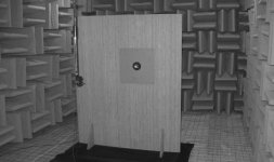
Anechoic -just to confirm, they always have been. Apologies, I should have mentioned it, I'd just assumed it was known. FWIW, you can see part of the chamber & baffle in a photograph in the 5.3 datasheet.
Last edited:
Only a peripheral part, mainly on characteristics, requirements etc., which they're free to accept or reject as they see fit.Scott, I'm following this thread with great interest and I was wondering since you were/are a part of the development team behind new driver, can you share some preliminary listening/sonic impressions or maybe a comparison with some of the existing MA drivers ?
If I understand correctly, it could fit into Joan enclosure ? Does it mean it could also fit in one of the existing horns of the Megalith family, or a new family member is under development ?
I'm afraid I don't really do subjective comments because anything I could say would be fairly worthless -outside the obvious, what I hear is unlikely to be what anybody else hears. Broadly speaking, it's like a bigger 10.3 / CHR-120 / 1st generation (alloy cone) Alpair 12 in its general performance, with more in the way of LF capability / headroom however.
Re Joan, I'm afraid I don't know yet -I'm still down with summer 'flu that isn't clearing up, so not yet checked properly. A new megalith is in the works, albeit slightly stalled right now for the same reason. Hoping to get the preliminary details to the long-suffering Dave by the end of the week though.
Anechoic -just to confirm, they always have been. Apologies, I should have mentioned it, I'd just assumed it was known. FWIW, you can see part of the chamber & baffle in a photograph in the 5.3 datasheet.
Attachments
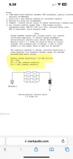
Take a look of this enclosure design for MA200-M:
https://www.markaudio.com/wp-content/uploads/2024/07/MA200-M-Keele-aligned-EBS-vented-box.png
How about using Alpair 5.3 or CHN-40 as tweeter in 3d-printed chamber etc above MA200-M in that plan. Maybe first order PLLXO?
Scott: Is this EBS alignment designed to be used near or in room corners?
https://www.markaudio.com/wp-content/uploads/2024/07/MA200-M-Keele-aligned-EBS-vented-box.png
How about using Alpair 5.3 or CHN-40 as tweeter in 3d-printed chamber etc above MA200-M in that plan. Maybe first order PLLXO?
Scott: Is this EBS alignment designed to be used near or in room corners?
Attachments
so, you put a 7.5ohm resistor in front of it to push the qts high.........................
I have dabbled in subs, some ebs designs (extended bass shelf) would tune to the speaker / box F9.
I have dabbled in subs, some ebs designs (extended bass shelf) would tune to the speaker / box F9.
Last edited:
- Home
- Loudspeakers
- Full Range
- New Markaudio MA200 8" Driver

