I don't have a measuring microphone. Only a bedroom studio with a selection of vocal and guitar mics. Will have to do. Driver should be here in a few weeks.
That could do, as long as you stay with the same mic before and after. You probably have a mic that is flat enough thru the range of interest. Let me know what you have, maybe I can help pick one.
I have two dynamic noname mics, one Shure SM57 clone, and one Beyerdynamic clone. I don't like to pay too much for stuff.
SM57 clone is cold and boring, not very detailed.
One of them is very similar to this one and is great for vocals.
Beyerdynamic TG-X61 Vocal Microphone from Sound Exposure - The leading Pro Audio and Broadcast Superstore
And one Condensor: MXL V67G. MXL® Microphones - MXL V67G Large Capsule Condenser Microphone
Like any cheap condensor. I should exchange all the caps and maybe upgrade the membrane, but have not gotten so far yet. First I need to hear the sound properly, so great horn speakers are first on the list, then record studio album. 😛 The MXL V67G is picks up everything reflection in the room, so I always berry whatever I am recording in pillows. Not my first choice for measurement perhaps, but the MXL will record the end result very nice.
Last edited:
The back cup on the driver is undoubtedly put on last in the assembly. I don't know how it is held on, but maybe just a few screws. Perhaps a swagged metal joint around the perimeter.
Be careful about metal chips and splinters being drawn into the magnet and the gap.
_-_-
Be careful about metal chips and splinters being drawn into the magnet and the gap.
_-_-
Bear, yes I should tape the gap like with a recone.
Pano, the MXL it is.
Still thinking about replacing the magnet. Radian, what is your theory, that low frequency will only be affected by increased backchamber and not by a stronger magnet, based on?
Pano, the MXL it is.
Still thinking about replacing the magnet. Radian, what is your theory, that low frequency will only be affected by increased backchamber and not by a stronger magnet, based on?
The back cup on the driver is undoubtedly put on last in the assembly. I don't know how it is held on, but maybe just a few screws. Perhaps a swagged metal joint around the perimeter.
Be careful about metal chips and splinters being drawn into the magnet and the gap. _-_-
Yes be careful. Easiest way is to fill the air gap with hot wax. Make shure it flows
all the way down filling the whole cavity up. Let it cool down long
enough. After your work is done the splinters can be scraped off from the
hard wax surface. Then just reheat the unit and all wax flows out. It leaves a
very fine layer on the metal wich is a great long term corrosion protection.
Klaus
I am still not certain how it should look like inside. Are you avoiding the question, Radian? 😉
Is it just to widen the hex-shaped hole to almost an inch wide, and make sure the diaphragm dome have room in the magnet? Or does the dome-shaped chamber in the magnet need to be larger as well?
With backchamber, I assume we are talking about the dome-shaped hole in the magnet behind the diaphragm, together with the hex-shaped hole, that needs to be widened.
Hot wax seem like overkill to prevent splinters in the maget gap. Tape should suffice. Unless the hole does not go through to the other side. I have to look at it first.
Last edited:
Bear, yes I should tape the gap like with a recone.
Pano, the MXL it is.
Still thinking about replacing the magnet. Radian, what is your theory, that low frequency will only be affected by increased backchamber and not by a stronger magnet, based on?
The magnet has not changed any mechanical properties of the driver.
Max excursion, moving mass, stiffness of the surround all stayes the same.
For a given spl at a certain frequency we need X amount of excursion.
This will be the same with a stronger or weaker magnet. If lets say at 110db
the coil leaves the homogenous region of the gap it will do this with either
magnet and exhibit therefore the same distortion. The only thing that is
different with the two is that you do not have to put as much wattage into
the coil of the stronger magnet driver. If you would drive the K55 with a
2 Watt single ended tube amp than the stronger magnet would benefit you
with more headroom, but with anything more than 10 Watt it would mean zip.
If you are a die hard purist refusing to alter the signal even a bit to raise the
lowest region of the horn than you might want to copy Dietmar's driver exactly.
If you use a digital front end or a digital crossover of some sort
anyway then there is no need to add the stronger magnet.
I still doubt that the gain in the lower region is from the stronger magnet.
The before and after mesurments where made after all the modification:
Namely:
1. Stronger magnet
2. Bigger back chamber
3. 0.2mm distance ring under diaphragm assembly.
4. A few holes in the phase plug to lower the compression ratio
The two things that I see as causing a stronger bottom end are the
distance rings that gave a softer compiance resulting in a lower resonance,
and the bigger back chamber lowering the resonace also.
With the holes in the phase plug I got my problems because an additional
cavity of a few ccm should result in an unwanted resonace somewhere.
Anyway for me it's kind of strange to buy a cheap $100 driver to put a magnet
structure from another driver on it that probably cost twice as much.
Klaus
I am still not certain how it should look like inside. Are you avoiding the question, Radian? 😉 ..
Sorry I did not get that particular question.
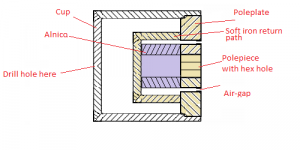
The hex shaped hole lies within the Alnico magnet which is basically a tube
extending all the way back to touch the cup. The cup is of soft metal and
builds the magnetic return path.
The problem is I don't know how that cup is hold in place. I have never seen
one open either as there is just no need to open it. Now the hex shape of the
hole might give away that the cup is screwed on. Just put an Allen wrench
in the hole and try to turn the cup counter clockwise.
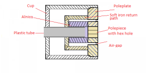
The neodymium magnet needs to have the exact same length than the Alnico
one because it needs to touch the cup for the mentioned magnetic return.
The center pole piece is sometimes glued to the alnico magnet. You need to
get it off and put it on the new neodymium magnet. It would be great if you
find a neodymium magnet in the form of a tube, then you would not have to
drill a hole through it. I don't even know if it can be done with a brittle material as Neodymium.
.
Radian,
Do you mean to add the 0.2mm spacer is sufficient to increase the size of the back chamber?
Or do you mean that the hex shaped hole must also be increased for the back chamber to be large enough for 100Hz frequencies?
All this talk about drilling and replacing a high tolerance hex-shaped magnet with a random neo magnet seem more complicated than to just replace it with a Peavey structure. I would just have to live my choice to not follow the alnico hype. 😛

Are you sure the cup is the magnetic return? If so it must be heavier
than I seem to recall from years ago...
...Perhaps it is a bit anemic, and there is some loss there??
I'd expect that for an alnico magnet there would be an internal path with a flat (round) plate on the back with the center having a cylindrical return to the center pole piece, forming the gap. The cup being for weather protection and cosmetics.
Alternately the center piece being an alnico slug, and the return goes to the outer part, like early JBL drivers.
Anyone got a side shot of the driver??
As far as fitting a neo driver, it would only need a new return path, the front pole plate would remain the same... in any event there could be spacers of nice soft iron to make up the missing dimension, or just pile on extra neo magnets? 😀
Radian,
Do you mean to add the 0.2mm spacer is sufficient to increase the size of the back chamber?
Or do you mean that the hex shaped hole must also be increased for the back chamber to be large enough for 100Hz frequencies?
All this talk about drilling and replacing a high tolerance hex-shaped magnet with a random neo magnet seem more complicated than to just replace it with a Peavey structure. I would just have to live my choice to not follow the alnico hype. 😛
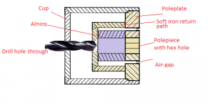
How much easier can it get than to drill one hole in the Cup?
The 0.2mm spacer just clamps the surround more on the outside
giving it more freedom to move and making it therefore also less
stiff for a lower resonance.
Attachments

Thank you for the detailed picture. This make it look easier, but there is one thing. Reshaping magnets is tricky because it can screw up the magnetism. I might end up having to replace the magnet anyway.
Wait, you said cup. Do you mean I should widen the hex shaped hole or just open up the cup on the back side, and keep the width of the hex hole?
You also mentioned replacing the center magnet with a neo magnet. Where did this idea come from? Peavey does not even have neo magnets in their compression drivers, so it cannot have been tried yet by your friend.
Last edited:
Are you sure the cup is the magnetic return? If so it must be heavier
than I seem to recall from years ago...
...Perhaps it is a bit anemic, and there is some loss there??
Yes Bear, The cup is indeed quite light weight and if it is not the return path
then the driver probably looks something like in the pics.
I will ask Dietmar if he can take the Cup off one of my Drivers then we
will know more.
Attachments
Last edited:
Thank you for the detailed picture. This make it look easier, but there is one thing. Reshaping magnets is tricky because it can screw up the magnetism. I might end up having to replace the magnet anyway.
Wait, you said cup. Do you mean I should widen the hex shaped hole or just open up the cup on the back side, and keep the width of the hex hole?
You also mentioned replacing the center magnet with a neo magnet. Where did this idea come from? Peavey does not even have neo magnets in their compression drivers, so it cannot have been tried yet by your friend.
As the alnico is usually in a pipe form there should not be any reshaping
neccesarry if we drill from either of the sides. If it is in a full cylinder form then it gets more tricky.
.
It was just my suggestion to use neodymium if the stock Alnico will not
exhibit the desired results. I did it once on a Saba speaker. Neodymium magnets
can be bought in all forms and shapes. Getting within half a Millimeter
should not be a problem. The rest can be sanded down. Dietmar said he can
not hear a
difference between the alnico and the ceramic Version of the K55. He has
nice gear so it can not be blamed on inferior electronics.
With an aluminum diaphragm this might be different.
Our K55 will only be used in the lower region where it gets even more
difficult to destiquish between different magnet and diaphragm materials.

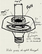
Here is a sketch that Dietmar made and I modified to illustrate the spacer
mod in English. It gets the diaphragm to 1mm max excursion.
Like so?
I am not sure you wanted a straight hole through.
Did his 130 holes in the diaphragm surround ever give any better result?
Attachments
Last edited:
The 130 Little holes in the surround was my Suggestion to lower FS. It did not work
because it coupled the air behind the diaphragm with the compression chamber in front
of it. I should have checkt the design of the driver more thoroughly. Something good
came out of it anyway because after Dietmar sealed the holes again with very elastic
glue it had more compliance. This raised the Output in the lower Region so we knew
we where on the right track with lowering FS but we just used the wrong method.
Then Dietamr hat the brilliant idea of putting the spacers in, which had the desired effect.
- Home
- Loudspeakers
- Multi-Way
- New ideas for K-55 and PD-5V compression drivers