I can suggest to use this 1:1 interstage transformer 110Hy
as input transformer.
And to order some L of 250Hy for 10-15mA DC current.
Low capacitance and as much low Rdc.
It can ber useful for many other tubes...
as input transformer.
And to order some L of 250Hy for 10-15mA DC current.
Low capacitance and as much low Rdc.
It can ber useful for many other tubes...
Zoran & 50AE - Thanks again for the help. What is the appropriate current needed from the driver tube? The RE084 will deliver 5-7mA, which 50AE indicated was too low. What is the desired amount of current? Thanks, Pat
Here is what I found for minimum driver current:
I >> A Cag 2 pi f Vpk
A = 12.5
Cag = 6pF
Vpk =
I = 12.5 * 6x10^-12 * 2 * 3.14159 * 90 * 20000 = 0.0015613 = 0.85 mA
Then, someone mentioned that we want 2 or 3x the calculated current of 0..85mA, so let's take 3 * 0.85mA = 2.5mA
Assuming my calculations are correct, then 5mA from the re084 driver is more than sufficient.
Pat,
I'm afraid, not the power tube Miller capacitance will be the biggest problem.
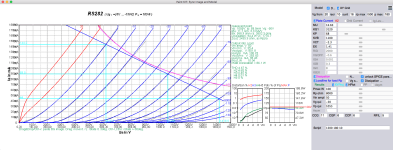
Are you read carefully RS282 datasheet in your #1 post?
Search "Gitterstrom".
Rob used this tube as preamplifier, so output power was almost subsidiary.
If you want significant power, each large transmitter tube eats the grid current... and requiring power to driving.
I think, without beefy driver, or CF/SF this tube cannot be used as good power amplifier.
p.s.
Here is the 40mA anode current driver tube control the RS282:
https://www.jogis-roehrenbude.de/Leserbriefe/Volker_Kluft-RS282-Amp/strategos.htm
I'm afraid, not the power tube Miller capacitance will be the biggest problem.
Are you read carefully RS282 datasheet in your #1 post?
Search "Gitterstrom".
Rob used this tube as preamplifier, so output power was almost subsidiary.
If you want significant power, each large transmitter tube eats the grid current... and requiring power to driving.
I think, without beefy driver, or CF/SF this tube cannot be used as good power amplifier.
p.s.
Here is the 40mA anode current driver tube control the RS282:
https://www.jogis-roehrenbude.de/Leserbriefe/Volker_Kluft-RS282-Amp/strategos.htm
Last edited:
With this "driver" tube (no gain, low current, high impedance, high distortion ... ) this is the "ultimate" solution:

2.9W output with 100W power tube.
Worth it?
1:4 SUT, 10Y/801a, FET SF, fixed bias RS282 8k4 OPT (1200V B++) the simulation shows 14W output .... but with 8.6% distortion.
2.9W output with 100W power tube.
Worth it?
1:4 SUT, 10Y/801a, FET SF, fixed bias RS282 8k4 OPT (1200V B++) the simulation shows 14W output .... but with 8.6% distortion.
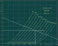
Thanks Bela, helpful. I have been emailing with Rob who uses the RS282 as an output tube SE at appr. 600V, 50A. As an alternative to the RE084, I could use an EML 12B or EML 20B. My interstage transformer has a max current of 30mA. Load lines of the EML 20B attached as an example of how I could use the tube. Thoughts?
Attachments

Thanks Bela for running that simulation. 8.7% distortion is too high. What is causing this much distortion.
My OPT (new from Alexander) is 9.6K primary. In talking with Rob, I would use 600V on the RS282, just like he uses.
My OPT (new from Alexander) is 9.6K primary. In talking with Rob, I would use 600V on the RS282, just like he uses.
"What is causing this much distortion."
With this spice model, the simulated distortion is high ... higher, than Zoran suspected.
The real measurement would be different ... but these large transmitter tubes aren't distortion champions.
With this spice model, the simulated distortion is high ... higher, than Zoran suspected.
The real measurement would be different ... but these large transmitter tubes aren't distortion champions.
This is not complet formulaHere is what I found for minimum driver current:
I >> A Cag 2 pi f Vpk
A = 12.5
Cag = 6pF
Vpk =
I = 12.5 * 6x10^-12 * 2 * 3.14159 * 90 * 20000 = 0.0015613 = 0.85 mA
Then, someone mentioned that we want 2 or 3x the calculated current of 0..85mA, so let's take 3 * 0.85mA = 2.5mA
Assuming my calculations are correct, then 5mA from the re084 driver is more than sufficient.
in short:
Cmiller = Cga x [ 1 + abs(-A) ], see wikipedia for the definition...
where A is stage gain, not mju (amplification factor) of the tube
this - in front of A indicates that is about phase shift of 180deg, (the sign is changing)for the any amplification single stage.
We have also Cgk capacitance
And these 2 capacitances forms Dynamic capacitance
Cdynamic = Cgk + Cmiller
Cdynamic = Cgk + { Cga x [ 1 + abs(-A) ] }
this Cdynamic has reactive Impedance @ given fo
XCdynamic = 1 / [ (2 x PI x fo) x Cdynamic ] in ohms
The driver has to be from lower Equivalent reesistance than XCdynamic - not to form RC passive filter...
and
ICdynamic = Cdynamic x ( dV / dt )
from these
ICdynamic(fo) = ( 2 x PI x fo ) x Cdynamic x Vin(p-p)
The value of input ac Signal is in peak-to-peak value and max value of that will be Vin(p-p) = 2 x Ug (negatve bias value as max. value for the input voltage of the tube...
This impedance is in parallel with input resistor of the tube Rg. It is a small value but it exists...
You have Rg in parallel with XCdynamic at the input.
So the total input AC Current swing P-P will be
Irg = Vin(p-p) / Rg
So the total input ac current P-P at some fo will be
Ip-p(fo) = ICdynamic(fo) + Irg
.
fo has to be calculated. I will post latter how.
But You can use 5 X more than say 20KHz as some minimum...
input values:
Fo = 100 Khz
VinP-P = 2 x abs(-Ug)
Cgk
Cga
Rg
.
NOTE:
Cga value for pentodes connected as triodes, is usually not given in the datasheets...
We find this value as low value. But this is bigger value in triode connecton of pentodes or beam tetrodes.
In some small tuve datas of pentodes capacitances are given for pentode and for triode opperation...

Driving Current (p-p) is not the only conditionAssuming my calculations are correct, then 5mA from the re084 driver is more than sufficient.
Driver equivalent output resistance has to be lower (for the desired fo say 100 KHz) than XCdynamic
For not to form -3db filter
goal is to have minimum phase shift and -db loss @ 20KHz
So we are not using 20 KHz as HF margin but minimum 5 X more, 100 KHz
.
That will mostly depend of Ri of driver tube as rougly Req in parallel with RLoad
Req = (Ri x RLoad) / (Ri + RLoad)
.
Ri of RE084 in working point is about 8750 ohm
Last edited:
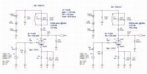
Example:
in these settings for RS282
input is 100Vp-p
output is 801Vp-p
Gain is
abs(-A) = 801Vp-p / 100Vp-p
A = 8
Cgk = 11 pF
Cga = 6 pF
Rg = 470 Kohm
Fo = 100 KHz
Vin(p-p) = 100 V
------------------
Cdynamic = Cgk + { Cga x [ 1 + abs(-A) ] }
Cdynamic = 65 pF
.
XCdynamic(fo) = 1 / [ (2 x PI x fo) x Cdynamic ]
XCdynamic(100KHz) = 24485 ohms
.
I made typo mistake in previous post about formula:
this is correct 🙁
.
ICdynamic(fo) = XCdynamic x Vin(p-p)
ICdynamic(fo) = Vin(p-p / ( 2 x PI x fo x Cdynamic )
ICdynamic(100KHz) = 4.08 mA (p-p)
.
IRg = Vin(p-p / Rg
IRg = 0.212 mA (p-p)
.
Idrv(100KHz) = ICdynamic(fo) + IRg
Idrv(100KHz) = 4.3 mA (p-p)
Attachments
Zoran - thank you very much for the education. This is extremely helpful. If I'm understanding the calculation for Idrv, then 4.3mA would be sufficient driver current and this takes into account the 100Khz (which is the factor of 5x 20khz).
If I were to use a different driver, say the EML 20B which can output 25mA with Rp=3k3, then this would definitely be enough current and also help with the phase issue, correct?
If I were to use a different driver, say the EML 20B which can output 25mA with Rp=3k3, then this would definitely be enough current and also help with the phase issue, correct?
The problem with L load of RE084 is that L load represents very high R load line
more than 250K
That is the almost straight load line tend to be parallel with X axis...
So, there is no "much" Io p-p at the Y axes.
From the graph og RE084 it is just about 0.3mA p-p
.
more than 250K
That is the almost straight load line tend to be parallel with X axis...
So, there is no "much" Io p-p at the Y axes.
From the graph og RE084 it is just about 0.3mA p-p
.
From the first sight - Yesf I were to use a different driver, say the EML 20B which can output 25mA with Rp=3k3, then this would definitely be enough current and also help with the phase issue, correct?
You can expect of about 100Vp-p after EML 20B since it has mju=20
(lets say the -A will be 18)
That will allow You to get more useful power from RS282...
.
But You can use RE084 for the preamplifier?
It has very low distortion of about 0.145 %
in allowed operation point of -3.4V Ug.
with 2:1 step down
-A of preamp wil be around 7.9 X
and impedance will be 8750 / 4 = 2187 ohms
?
Hold on 🙂
I found some informations about EML 20B tube.
Actually, one important set of parameters missing: Capacitances
(Probably it could be estimated based on similar tubes? Mu guess that is some RS series replica?)
.
Second I found 2 existing measured anode chrs graphs by manufacturer.
They should be compared to have more clear insight of the tube.
(And one additional measurement of similar tube - different version...)
.
That is expensive pair of tubes and no need to rush-in?
.
first from EML site:

second is labeled as EML but not from their site...

third is from Bartola measurements
BUT note this is for 20AM VERSION, not 20B version

4th is also from Bartola
note hater values in the graph of: 5V 1.5A
BUT this is also for 20AM VERSION, not 20B version

The graph is set to max Pa of 9W
.
EML 20B maximum values:
Vamax=550V
Iamax=60mA
Pamax=25W
filament
Vf=5V 5% (+-2.5%)
If=1.4A
(Wf=7W)
.
The graps should be compared with manufacturers measurements
and estimate more realistic capacitances than one proposed in the spice model in EML site and on Bartola model
.
citation from Bartola page about EML 20B
"Unfortunately there’s no capacitance data on the EML data sheet. I have to say that this is an area where they fall short. These days you would expect a detailed data sheet. That is not the case so far, I hope they improve on this in the future."
I found some informations about EML 20B tube.
Actually, one important set of parameters missing: Capacitances
(Probably it could be estimated based on similar tubes? Mu guess that is some RS series replica?)
.
Second I found 2 existing measured anode chrs graphs by manufacturer.
They should be compared to have more clear insight of the tube.
(And one additional measurement of similar tube - different version...)
.
That is expensive pair of tubes and no need to rush-in?
.
first from EML site:
second is labeled as EML but not from their site...
third is from Bartola measurements
BUT note this is for 20AM VERSION, not 20B version
4th is also from Bartola
note hater values in the graph of: 5V 1.5A
BUT this is also for 20AM VERSION, not 20B version
The graph is set to max Pa of 9W
.
EML 20B maximum values:
Vamax=550V
Iamax=60mA
Pamax=25W
filament
Vf=5V 5% (+-2.5%)
If=1.4A
(Wf=7W)
.
The graps should be compared with manufacturers measurements
and estimate more realistic capacitances than one proposed in the spice model in EML site and on Bartola model
.
citation from Bartola page about EML 20B
"Unfortunately there’s no capacitance data on the EML data sheet. I have to say that this is an area where they fall short. These days you would expect a detailed data sheet. That is not the case so far, I hope they improve on this in the future."
Last edited:

There are the settings You asked for specific points. I put the same RL = 9.6K, i didnt know inductance of Your piece just put 60Hy...
This is situation with undistorted input signal from ideal sim generator. I put the source impedance as RE084 Ri value of 8750 ohms
The HF roll of is dominant by Transformer Coupling factor (read capacitance and Leakage inductance...) more than higher Rsource value...
Add authomatic bias to reduce Supply voltage and to eliminate RC net in cathode - to isolate only inductance of primary as main factor in LF
If you search for Ale's measurements, easily found this:
https://www.bartola.co.uk/valves/2019/03/24/eml20a-driving-eml45b/
In this measurement Zin (10kHz):590k
590k impedance at 10kHz results about 27pF input (Miller) capacitance.
https://www.bartola.co.uk/valves/2019/03/24/eml20a-driving-eml45b/
In this measurement Zin (10kHz):590k
590k impedance at 10kHz results about 27pF input (Miller) capacitance.
- Home
- Amplifiers
- Tubes / Valves
- New idea: RE084 drives RS282