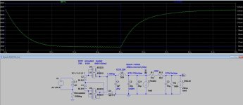
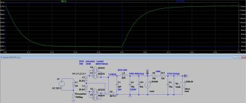
OK but it is not even 9.1K because it is for 9 ohm secondary load?Here are the parameters. Thoughts?
the impedance square ratio is 9100 / 9 = 1011
So with 8 R load it will be about 8090 R @ anode load
and with 7 R it will be 7080 R @ anode...
Anyway the slope will be slightly different, little bit more power but also more THD 🙁
...
The same Q for the power transformer - is it 2 x 800Vac with C.T (1600Vac)800-0-800 with 48R DCR for each secondary???
.
Please also write the values of power chokes L and Rdc
Is these values like on the PSUD schemais of power supply?
.
Thanks
OK
thanks
.
please check in the PSUD:
this 1st C in PS after rectifiers.
Has very high voltage peak at the start.
So the voltage rating of that 1st C should be more than that...
thanks
.
please check in the PSUD:
this 1st C in PS after rectifiers.
Has very high voltage peak at the start.
So the voltage rating of that 1st C should be more than that...
C1=1uF in Your schematic. Check the peak voltage on that C...The first C (large C, not the small 1uF c) is rated for 1100V.
I found my coil design notes. The power transformer has 1880T per leg on 212mm MLT with a 0.355 wire, so that should give 67Rdc to 70Rdc. Pat has the datasheet. Or he could place an ommeter on one leg.
I asked it, because each tube rectifier requires definite RDC for given current, so series resistance (on each anode) may be necessary (must to calculate its value).
BTW, Pat you want to use 866 as rectifier?
I use mercury vapour rectifiers, using them is not an easy thing.
Preheating requires for MV heaters, even few minute heating before the main PT (HV secondary) turn on.
BTW, Pat you want to use 866 as rectifier?
I use mercury vapour rectifiers, using them is not an easy thing.
Preheating requires for MV heaters, even few minute heating before the main PT (HV secondary) turn on.
I have been using 866 and 83 mercury rectifiers for 8 years without any issues. And yes, I preheat them each time before turning on HV.
Pat,
Are you read this?
https://www-radiomuseum-org.transla....html?_x_tr_sl=auto&_x_tr_tl=en&_x_tr_hl=en#1
That might explain the higher distortion at larger swing.
Are you read this?
https://www-radiomuseum-org.transla....html?_x_tr_sl=auto&_x_tr_tl=en&_x_tr_hl=en#1
That might explain the higher distortion at larger swing.
For given PS value of 887V, this is some simple configuration as example.
This is also could be used with existing transformer (one with 250Hy) load to 20B. But ONLY
1. IF it is capable for 35-40mA DC current trough primary.
2. In the configuration as Primary load to 20B anode, secondary just correcting the Load slope... NOT as interstage.
.
The main disadvantage in this configuration is huge dissipation at Rload to 20B. The same will be with almost any other topology
Because huge voltage drop is needed. For R Load to be warm and not to bring huge additional heat to the chasses and internal elements, 4 times of actual dissipation is the goal. And that is about 80W... 🙁
.
Other way is to use very useful power transformer to supply additionally 20B or other input tube.
BUT that will employ minimum 2 additional chokes in PS, and 3-4 capacitors. And of course it is not small space to add and organize at the present classes.
.
Anyway the amp will export about 7W, with 2Vrms input, with present OT. At the input of RS282 will be about 80Vp-p
so there will be little room for 10Vp-p more for not to exceed -45V of Ug and to stay in negative region of -Ug values. With a bit more power and more distortion... For sims I used the OT transformers datas from the topic.
.
If I can ask why it is Vb power supply voltage restricted for 887V?
Because max voltage values of PS capacitors?
.
Present power transformer can give a more Vb voltage with 866 rectifiers.
With all the same LC elements.
.
Just with different first C after the rectifiers, C1.
I checked Voltave peak +DC will be 1200V so the rated value of that C1 should be 1500V (1200V minimum)
.
OK 🙁
887V is so close...
I presumed that they rated to 900V... Probably some block Cs?
.
Take a note about this 1st C should be minimum 1200V rated, (better 1500V)
Cheers
887V is so close...
I presumed that they rated to 900V... Probably some block Cs?
.
Take a note about this 1st C should be minimum 1200V rated, (better 1500V)
Cheers
Pat,
Are you sure, that this PSU designed for power stage (and it is not made for a preamplifier)?
cLCLC type PSU (with these large choke values) has very high PSRR, but its impulse recovery is very worse.
Rather used with practically constant load current than large variable one.

If you use first cLC for power stage, and another parts for driver, the recovery time will be about 300ms, which is enough good.
BTW I suggest to omit second choke. Absolutely unnecessary strive to reach few mVpp hum.

Cons, that simple cLC (even so doubling second capacitor value) gives higher hum on B++.
If you raise first capacitor value (doubling), the hum would be acceptable ... and the B++ voltage will be higher too, which is better for RS828.

Are you sure, that this PSU designed for power stage (and it is not made for a preamplifier)?
cLCLC type PSU (with these large choke values) has very high PSRR, but its impulse recovery is very worse.
Rather used with practically constant load current than large variable one.

If you use first cLC for power stage, and another parts for driver, the recovery time will be about 300ms, which is enough good.
BTW I suggest to omit second choke. Absolutely unnecessary strive to reach few mVpp hum.

Cons, that simple cLC (even so doubling second capacitor value) gives higher hum on B++.
If you raise first capacitor value (doubling), the hum would be acceptable ... and the B++ voltage will be higher too, which is better for RS828.

the Rdc of the each secondaries 70 ohm is not only component transfered torectifiers?
Should be added Rdc primary x transformation ratio?
(Like in some rectifiers datasheets, and PSUD2 example)
Should be added Rdc primary x transformation ratio?
(Like in some rectifiers datasheets, and PSUD2 example)
- Home
- Amplifiers
- Tubes / Valves
- New idea: RE084 drives RS282