Here is the diagram of 2 stage RE084 + RS282
Look how the RE084 has low distortion with 5.8Vp-p input @ Ug=-3.5V (7Vp-p room for input signal...)
And with 250Hy in anode, with lower Hy in anode THD will be higher...
.
But observe how is distortion rises with decreasing of Io of RS282
With added 1K in series to the RE084 output resistance there are no visible rolloff on RS282.
Since there is no Cga for triode mode connection for RE282 I put 6pF. Probably there is higher value of Cga?
.
One of the the main issues in this sch is huge diference in supply voltages on power and input stages
Thatdeservs 2 separate power supplies... One main transformer with multiple taps on secondaries HV can be used.
To optimize that part and avoid another power supply transformer for input stage only...
.
I observe power from load at the anode of about 6.3W with 5.8Vp-p input signal (2Vrms cca.)
(Ioutp-p x Uoutp-p) / 8
That is without transformation loos and other losses...
.
Next step is to check same but with Cathode follower prior to power tube to see what is happening...
.
Yes that is another measured anode chrs diagram and should be compared to manufacturers one.If you search for Ale's measurements, easily found this:
https://www.bartola.co.uk/valves/2019/03/24/eml20a-driving-eml45b/
In this measurement Zin (10kHz):590k
590k impedance at 10kHz results about 27pF input (Miller) capacitance.
.
But where is the transfer graph You refering to?
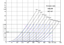
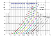
Done some photoshop scaling to compare 3 diferent anode chrs. for 20B Emission Labs tube.
The curves are from the same "family", slopes are similar, but there are major differences...
So it could imply to the poor constancy of specimens or something else.
Bare in mind that capacitances are missing...
These issues can not go with very expensive pair of tubes... 😳
.
Somebody try to think about the 20B tube origin?
It has larger ratio of Wf / Wa-max like some Telefunken DHT models?
.
Please see the compared anode chrs:
Note about -Vg it is not the same step and not starting from 0 in some graphs
.
(Why don't they sett the axes numbering in some round values;
50V, 100V etc... 10mA 20mA... -1V , -2V etc.
Like brands always did before? 👎)
Attachments
Zoran, putting aside the tube curve variances, axis numbering, etc, and of couse the missing capacitances, I have used EML tubes in the past and they are very good. Built like a tank and also sound very transparent, low distortion. They need 100+ hours of break-in to show their stuff, but otherwise good. I am thinking of the following operating point on the curve below.
Attachments
Assuming 2Vrms in, You should expect 2Vrms x 2.828=5.6568 Vpk-pk in, giving output 20 x 5.6568 = 113Vpk-pk output. Distortion will be low. Second harmonic below -60dB at 1 kHz .Here is a proposed operating point of -4Ug, 320V, 25mA. Gives a little headroom with a -2V input (no input transformer). Output would be approximately 160Vpp.
Thoughts?
https://i0.wp.com/www.bartola.co.uk/valves/wp-content/uploads/2019/03/EML20A-driver.pngBut where is the transfer graph You refering to?

Sorry, I previously read the #45 data.
EML20a:
517k impedance at 10kHz results about 30.7pF input (Miller) capacitance.
About a decade ago I measured for my friend EML20AM (CCS loaded on breadboard).
This picture shows 150Vpp.

This is very good VAS stage tube.
This picture shows 150Vpp.
This is very good VAS stage tube.
So, it looks like the 20B will be a fine driver tube. I will go with it.
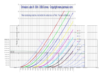
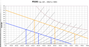
Here is one of my final questions: For the RS282 output tube. I would prefer to use 600v instead of 900v? Why, two reasons 1) my existing chassis supports the 600V transformer. If I were to use the 900V power transformer, then I would need to. modify the chassis and 2) If I use 600V on the RS282, then the same power transformer with less voltage drop would be used for the driver tube. So, assuming 600V @50mA Ug=-25V (see attached, blue lines), what would be the expected output watts? My math goes as follows:
480Vpp/1.41 = 340V
340V/sqrt(9.6K/8)= 9.82V
Pout = 9.82 * 9.82 / 8 = 12W
Does this look right?
Attachments
Wrong.
Double wrong.
If you choose 600V (615...625V B++ depending of primary DCR), 50mA operating point at -about- -25V grid voltage, the "upper" swing peek will be at -50V, not -55V.
The anode swing will be about 420Vpp.
The RMS value of this voltage is 148V.
The secondary voltage will be 4.27V RMS, so power 2.28W.
The simulation is more pessimistic, only 1.94W (due to the OPT losses).
Last edited:
I love you, Bela. I love you, Bela. If I say it enough times, I will start to believe it. 😉
Well, 2W is not what I have in mind. So, the highest voltage I can achieve is 900V. @50mA Ug=-45V gives 870Vpp. RMS = 307V. 307V^2 / 9.6K = 9.8W
Well, 2W is not what I have in mind. So, the highest voltage I can achieve is 900V. @50mA Ug=-45V gives 870Vpp. RMS = 307V. 307V^2 / 9.6K = 9.8W
Sorry but no,https://i0.wp.com/www.bartola.co.uk/valves/wp-content/uploads/2019/03/EML20A-driver.png
View attachment 1307598
Sorry, I previously read the #45 data.
EML20a:
517k impedance at 10kHz results about 30.7pF input (Miller) capacitance.
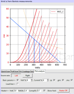
this is the position of cursor datas.
I just checked with same spice model on Tools software.
marked point close to the X axes in -6.5V refion.
With a same spice model
And not even in the working point of tube...
BUT
I changed values of capacitances with a different result.
Please take look
.
Batola most ligtly leave default values of initial capacitances in tools software on oppening.
CCG=3P CGP=1.4P CCP=1.9P
.
.
i put capacitances to more realistic values but very say "random"
CCG=8P CGP=7P CCP=6P
.
Found some datas based on Pa beause of the size of anode and similar heating values
but 20B has significantly higher mju factor, that implicates to more dense grid layers, closer to aeach other and more grid surface?
So the capacitnaces from grid to othet electrodes can be higher?
I dont know...
🙁
RV210 PX25
25W 25W
Cgk = 7.6 8.3
Cga = 5.1 14.8
Cak = 3.2 11.4
u=5 9.5
Last edited:
As I wrote in #7 post: voltage doubler.1) my existing chassis supports the 600V transformer. If I were to use the 900V power transformer, then I would need to. modify the chassis and 2) If I use 600V on the RS282, then the same power transformer with less voltage drop would be used
Read in this topic #35 post:
https://www.diyaudio.com/community/...led-300b-push-pull.311357/page-2#post-7677221
Voltage doubler from '51.

Use similar with existing PT.

Thanks a lot.
I am not in this matter sorry that i am asking, but could You measure static Cs(fo) from Grid to Cathode?
.
With high voltage, dynamic mode, Cga capacitance that You measured probaby will be higher?
Probably around PX25 of 14-15pF?
I am not in this matter sorry that i am asking, but could You measure static Cs(fo) from Grid to Cathode?
.
With high voltage, dynamic mode, Cga capacitance that You measured probaby will be higher?
Probably around PX25 of 14-15pF?
Dont worry much about 20BZoran, putting aside the tube curve variances, axis numbering, etc, and of couse the missing capacitances, I have used EML tubes in the past and they are very good. Built like a tank and also sound very transparent, low distortion. They need 100+ hours of break-in to show their stuff, but otherwise good. I am thinking of the following operating point on the curve below.
You can set the tube pretty much very flexibile with very good results...
This is how approh. RS282 will behave in Your available vorking power supply condition, with existing output transformer of 9.6K load.Well, 2W is not what I have in mind. So, the highest voltage I can achieve is 900V. @50mA Ug=-45V gives 870Vpp. RMS = 307V. 307V^2 / 9.6K = 9.8W
Static simulations are about 6.9W with old school THD=5.17%
.
These 900V limit implicate fixed bias opperation, and Vdc drop @ Rdc primary of OT...
So that is one additional negative power supply and pair of quality high voltage Capacitora at the very input of RS282
.
But this is staic only, without dynamic sims and without losses in the OT transformer.
This is also with abstract undistorted input, in real circuit, the input to the tube wil have some distortion, slight, but will have
and this will be significantly higher in conjuction with RS282.
I spot that even with very low ditortion of RE084 RS282 does not react good in THD way... Even if I put the Ri of the RE084 as source generator Ug... I will emulate with 20B...
.
The key question about RS282 are:
- do You already have the tubes?
- how many pairs?
- and in what condition the pairs are?
I have one pair of RS282 tubes. I don't own a tube tester, but supposedly they were NOS. We'll see.The key question about RS282 are:
- do You already have the tubes?
- how many pairs?
- and in what condition the pairs are?
So You want te tubes last longer since You have one pair? 😉
Average level of listening power probabbly will be 1-2 W?
From that settings should not be close to optimal and max anode power, but lower. Since the tube will have constant emission in working point. It is not the same if the Pa is 58-60W or 100W max...
So maybe these settings, based on Your power supply requirements are propper?
.
The first thing is to form the output tubes. Put them on heating for 2 days. Just heaters nothing more. All other electrodes connect to ground.
.
After that put some smaller Anode voltage and negative grid bias but just for 5ma. For day or 2. To fill the first layer of anode more uniformly, that will prolong the tube life and wilk result in better sound in general... 🙂
.
What is the DC resistance of the primary and inductance of primary, of output transformer of 9.6K?
Last edited:
- Home
- Amplifiers
- Tubes / Valves
- New idea: RE084 drives RS282