Thought I'd drag up this thread as I started today on my fonkens. this is my first speaker build - the nights spent wondering about what to build are maybe harder than actually building! Anyway, my cunning plan is to build a regular fonken and then build the slim tower with fonken tuning as well for comparisons. I have some drivers to come from Dave.
Pics:
1st up is the cut material. I made this from 15mm birch ply so resized a few dimensions to suit:
Next are the braces. I have rounded over the edges of all the holes: have i done enough holes do you think? The brace is 15mm and is the one thing I didn't make allowances for being bigger than spec'd in the build.
This was a dry assembly of the build to make sure I got my calculations right. Not shown are the front baffles. I glued 2 sheets of 15mm together for these and I might just pass it through the planer a few times to bring down that thickness a little. Maybe 25mm would be better.
from the front:
The backs - the hole (rounded over on the inside) is for the mounting plate for the speaker terminals.
And another view with the back out of the way.
Comments etc invited please!
Fran
Pics:
1st up is the cut material. I made this from 15mm birch ply so resized a few dimensions to suit:
An externally hosted image should be here but it was not working when we last tested it.
Next are the braces. I have rounded over the edges of all the holes: have i done enough holes do you think? The brace is 15mm and is the one thing I didn't make allowances for being bigger than spec'd in the build.
An externally hosted image should be here but it was not working when we last tested it.
This was a dry assembly of the build to make sure I got my calculations right. Not shown are the front baffles. I glued 2 sheets of 15mm together for these and I might just pass it through the planer a few times to bring down that thickness a little. Maybe 25mm would be better.
An externally hosted image should be here but it was not working when we last tested it.
from the front:
An externally hosted image should be here but it was not working when we last tested it.
The backs - the hole (rounded over on the inside) is for the mounting plate for the speaker terminals.
An externally hosted image should be here but it was not working when we last tested it.
And another view with the back out of the way.
Comments etc invited please!
Fran
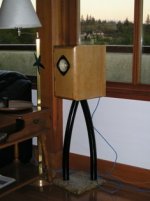
Looking great, Fran
My that's quick work & looks stunning! Can't wait to see the grain on these!
Keep up the great work - I'm eager to hear these!
My that's quick work & looks stunning! Can't wait to see the grain on these!
Keep up the great work - I'm eager to hear these!
Thanks john,
I'm think eventually for these to be cream and black like the rebuilt Lenco deck. But I'll need to listen a bit first!
Fran
I'm think eventually for these to be cream and black like the rebuilt Lenco deck. But I'll need to listen a bit first!
Fran
woodturner-fran said:Next are the braces. I have rounded over the edges of all the holes: have i done enough holes do you think? The brace is 15mm and is the one thing I didn't make allowances for being bigger than spec'd in the build.
You have made enuff holes that the 3mm difference should not be a problem. There are a few places thatthe holes are a little closer together than i'd put them, but they are in a less critical area.
dave
PS: Drivers in the mail 75 min ago....
Cool!!
I know some of the holes worked out a little close! But I wanted to leave a fairly solid stretch between the back of the driver and the back plate.
Measurements all check out on dry assembly though (better than I'd hoped for too down to +/- 1mm on most areas).
One bit of me says do a screw and glue on the final assembly and the other bit says glue only but with biscuits. What is best or does it matter. These will most likely be filled, sanded and sprayed with an automotive finish
Fran
Yeh, I forgot about your automotive paint finishes - looks great on the Turntable - I think they would look sumptuous in high gloss black, like a piano finish!
Nice fran!
And motivating...
Has anyone tried building these out of hardwood?
Or do they need to be baltic birch?
I'm thinking as close as all the bracing is, maybe any resonance will still be out of the pass-band?
(I have just enough 3/4 oak to make a pair, & just enough $ to order a pair of drivers from dave...)
Robert 🙂
woodturner-fran said:One bit of me says do a screw and glue on the final assembly and the other bit says glue only but with biscuits. What is best or does it matter. These will most likely be filled, sanded and sprayed with an automotive finish
IIRC, Chris (i'm nor allowed to build anything anymore), says just glue -- no biscuits, no screws -- leaves a stronger cabinet.
dave
Cabinet lay-up
Nice work Fran
Here are my thoughts for the final assembly if you have not completed it yet. The primary holding strength comes from the glue, no doubt about it. From a practical perspective if you have a complicated object you are assembling you need to have a lot of clamps and a very fast process or a way of helping the process out. As you know once you start gluing you have to go all the way through and get it finished before the glue starts to dry.
In the case you describe the biscuits are nice to keep glue joints lined up and in the right place when clamp pressure is applied. A glue joint that slides a bit under presure is a problem later.
For me if the joint is going to show I would not use screws and I would use biscuits or splines to keep things lined up (make sure you will not have the biscuit show when you radius the edge later).
Screws do a nice job of eliminating the clamps all together. As you indidcate you are planing on filling and finishing with a solid colour finish later. In that case I would do a complete dry lay with screws then disassemble and glue and re-screw. The dry lay helps to set up the assembly pattern gets the screw holes drilled and makes the gluing a little easier. Once the glue is dry and stable I would remove the screws fill the holes and radius the corner with a 1" roundover bit. do a final filling and sanding to prep for paint.
Good luck
Hello serenechaos
Yes I have made these cabinets out of solid wood. I used fine edge grained Douglas-fir from British Colummbia Cdn. This build is not a straight forward build as all the joints show. The final product is very nice and worth the effort. If you do go for it send me a PN and I can forward some photo's of the build and clamp up. Here is a picture of the finished project.
Attachments
Re: Cabinet lay-up
If a Fonken is built with a round-over instead of the champher, the port length needs to be adjusted. As well, to get the same diffraction benefit a 2" radius round-over is required.
Scott, did you get these things fixed up -- did you manage to repair them after the crack developed? It would be a shame to not keep these beauties playing on.
dave
SCD said:radius the corner with a 1" roundover bit
If a Fonken is built with a round-over instead of the champher, the port length needs to be adjusted. As well, to get the same diffraction benefit a 2" radius round-over is required.
... dolid wood.... The final product is very nice and worth the effort.
Scott, did you get these things fixed up -- did you manage to repair them after the crack developed? It would be a shame to not keep these beauties playing on.
dave
Dry assembly with the screws was exactly what I was going to do. In fact, I glued together the side panel asemblies and the double baffle exactly thing way. Then disassemble and glue back up again. I intend cutting back the pots just as per the plans but will do that at the end on the table saw.
I was just wondering whether I should just leave the screws in or not. If this was any other type of cabinet work the screws would be rebated, filled and left in.
I have 2 more enquiries:
1. That wool felt stuff thats recommended - is thats whats also known as will wool or linta felt? The stuff that was commonly used in upholstry work?
2. Internal wiring - I tend to use solid SPC in teflon for any of the wiring in the valve stuff I've done. Would that be OK here?
Fran
Hello David:
Yes, I did adjust the port length, good point to highlight. A round over of greater than 1 inch is a bit beyond most common shop machinery. I am not sure what the difference in ripple would be. I just like the presentation of the round over even if it is a bit of a compromise.
I have not been able to find the time to get back to the audio side of things for a long while. It seems the list of priorities and other stuff gets longer rather than shorter. I do intend to complete a few projects this spring. Maybe I can get the cracks worked out of these boxes.
Hello again Fran:
Regarding the screws: I do not think it really matters, if there is a bit of glue in the screw hole it will stay quite solid. The thought I would focus on is making sure the chamfer process does not cut the screw. (I was suprised when I revealed the biscuits when I made the round overs on my bipoles.)
I used a recycled felt on mine. the stuff is fairly dense and about 15mm thick, cuts with scissors. I am not sure of the names you
describe. Someone else may have a helpful comment.
I used CAT5 wire for the internals in mine. I first tried a single run and settled on a double run. I like to tack it in the corners or sides of the box with blobs of hot glue before I do the final glue up. That keeps it from rattling around later.
woodturner-fran said:1. That wool felt stuff thats recommended - is thats whats also known as will wool or linta felt? The stuff that was commonly used in upholstry work?
wool felt is fine -- you should have some samples (recycled) early next week. Someone posted a pic of the wool felt they got from an upholstry shop and it was identical to some of the recycled out of old speakers i use.
dave
Many thanks for all the advice fellas. I did the dry assembly tonight - all screwed together in advance of glue up.
I'm happy enough with it all - except for the front baffle. I think its gonna be really tight with the 24mm thickness. Right now I'm looking at a baffle width of 130mm instead of the 137 spec'd in the plans. The PDF from fostex says the width is 117mm so hopefully I should be alright - what do you guys think?
Thats about all I can do until the drivers arrive. I have to do the cutout on the brace so that it butts up tight to the driver - and I need to drivers to do that.
Fran
An externally hosted image should be here but it was not working when we last tested it.
An externally hosted image should be here but it was not working when we last tested it.
An externally hosted image should be here but it was not working when we last tested it.
I'm happy enough with it all - except for the front baffle. I think its gonna be really tight with the 24mm thickness. Right now I'm looking at a baffle width of 130mm instead of the 137 spec'd in the plans. The PDF from fostex says the width is 117mm so hopefully I should be alright - what do you guys think?
Thats about all I can do until the drivers arrive. I have to do the cutout on the brace so that it butts up tight to the driver - and I need to drivers to do that.
Fran
One last thought
Hello Fran:
Looks good so far
You might consider somehow finishing inside the port slots early. I found it to be a bit of a bear to get my finish inside those slots afterwards.
Hello Fran:
Looks good so far
You might consider somehow finishing inside the port slots early. I found it to be a bit of a bear to get my finish inside those slots afterwards.
Yeah, I was wondering about that. Don't think it would look so good with a black speaker and bare wood visible on the slots.
will keep it in mind,
Fran
will keep it in mind,
Fran
I ended up using a brush insided the slots. Put a few coats on then went to the final outside shell finish. I just could not get the spray gun to adequately get material in the slots
Most likely thats what I'll end up doing.
This is an addictive project. Its very easy to get carried away and glue up something a bit too quick!! This is a classic example. I glued up the side panels last night, and really I should have painted them first.
SCD/Dave - what do you think about the 130mm front baffle width, 24mm thickness and whether I should take it down a bit so that the baffle is wider?
Fran
woodturner-fran said:SCD/Dave - what do you think about the 130mm front baffle width, 24mm thickness and whether I should take it down a bit so that the baffle is wider?
As far as the front goes it will reduce wiggle room for getting the driver in (i measured 25mm total on a set of built Fonkens... the extra baffle thickness means you have half that. Sonically the slightly larger bevel is a positive. Make sure you set the depth of the cut from the back of the box to ensure vent length is consistent.
Probably of greater significance is the opening on the back of the baffle.
dave
- Home
- Loudspeakers
- Full Range
- New Fonken pair is born.