if you are using a solid state rectifier the 250v PT may be OK. it depends on the current rating of the transformer.
I have two 7247 and four 6BQ5 tubes. And two 6N2 and four 6P15.6N2P is similar to a 12AX7 (both halves hi-mu triodes) while the 12DW7 has 2 different triodes, one hi-mu the other low-mu. and the heater pinout is different. no go.
In the last assembly "the whistle" disappeared, so I believe I have solved this problem.The "whistling" means the amp is working properly but the feedback wires need to be swapped as detailed in an earlier post.
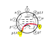
6p15 is close to EL84 but g3 needs to be connected to the cathode by wiring pin 6 or pin 1 to pin 8 on the back of the socket.
https://frank.pocnet.net/sheets/113/6/6P15P.pdf
https://frank.pocnet.net/sheets/113/6/6P15P.pdf
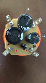
I do not have the original capacitor. I use an arrangement like the one in the attached photo.If the cap was properly installed it may be counterfeit.
Attachments
How is this?6p15 is close to EL84 but g3 needs to be connected to the cathode by wiring pin 6 or pin 1 to pin 8 on the back of the socket.
Attachments
R13 or it's connections faulty ? Or the cap connected to the B+ chain ? This cap is supposed to decouple the cathodes of the EL84 tubes where the voltages are nominally 13.5 VoltThe 100UF 25V capacitor exploded after a few moments of use of the device. He was mounted with polarity equal to the others. What may have happened? The amplifier continued to work until the fuse opens. Does anyone have any tips of what should I check before calling it again?
100uF 25v is meant to be a cathode bypass cap for the output stage. If it's in the power supply it is seeing 300+ volts and will explode.

I have two 7247 and four 6BQ5 tubes. And two 6N2 and four 6P15.
As you know 7247/6BQ5 are the “right” tubes for ST35. I suggest you use those to get your amp working properly before trying any other tubes.
Without redesign of the circuit I doubt that the 6N2 (with two 12AX7-like triodes) will work properly in the ST35 (even if you work out the heater pins correctly) due to the fact that the ST35 circuit is functionally requires 12au7 triode characteristics in the second triode that t2 in 7247 provides.
@dubadub stated that 6P15 is close to 6BQ5/EL84 in characteristics. This is true for the plate behavior at a much lower screen grid (g2) voltage than what you encounter in the Ultra Linear arranged ST35. So, it is possible that your 6P15 will red-plate in the ST35 at specified B+ of 385 Vdc, due to excessive plate and screen current. Be careful if you try it, and let us know what you found. Fortunately 6P15 also needs less negative bias than 6BQ5 at the same plate voltage, so your cathode bias resistor designed for 6BQ5 would result in higher value of negative bias than is ideal for 6P15.
Good luck.
Last edited:
Here's ST35 schematic:

You can see where the cathodes (pin 3) of the output tubes connect to the Cathode Resistor(95R) and Cathode Bypass Cap(100uF 25V) and also connect to the heater circuits. This elevates the reference voltage of the heater supply to the same voltage as the output tubes' cathodes, prob 10v or so.
Reading through the Dynaco ST35 Manual it looks like the 100uF 25V cap is part of the multi-section cap - you can see the 95R Cathode Resistor connected to Tab 4 at the bottom of Page 13. The schematic is a but blurry but I assure you the + side of the 100uF 25V cap should be connected to all 4 output tubes' cathodes and the - side to Ground, and the 95R resistor should share the same connections, one end to all 4 cathodes and the other to Ground. If your cap exploded it may have been wired backwards or it may have had HV from the power supply because of mis-wiring.
The schematic is not very clear but I believe the filter cap is the 40uF cap after the 50R resistor.
There should be a little dot on the junction to the Left of the 50R power resistor, but not to the Right.

here's a better sch.
There should be a little dot on the junction to the Left of the 50R power resistor, but not to the Right.
here's a better sch.
They always have been. The first drawing I posted was bad.
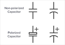
All caps in the power supply are polarized, as are the bypass caps. Only the caps on the PCB are film-type non-polarized.
All caps in the power supply are polarized, as are the bypass caps. Only the caps on the PCB are film-type non-polarized.
Sorry, in this new diagram, it shows that they are polarized electrolytic capacitors.
All the power supply capacitors are polarized electrolytic types.
These four C8 capacitor sections were originally all in one quad can.
The 100UF 25V capacitor exploded after a few moments of use of the device. He was mounted with polarity equal to the others. What may have happened? The amplifier continued to work until the fuse opens. Does anyone have any tips of what should I check before calling it again?
@AlCarlos,
The capacitor that exploded is probably in place of C8D. The mode of failure is likely installed with wrong polarity, although a wrong connection to B+ will also do that. I can’t make out the traces on your adapter PCB for multicap C8 replacement, but make sure the polarity of the substitute C8D is correct, connections with positive terminal towards the power tube cathodes, negative towards ground.
Have you been able to exchange your power transformer? What transformer did you get in exchange?
Yes, I will keep everyone informed.@dubadub stated that 6P15 is close to 6BQ5/EL84 in characteristics. This is true for the plate behavior at a much lower screen grid (g2) voltage than what you encounter in the Ultra Linear arranged ST35. So, it is possible that your 6P15 will red-plate in the ST35 at specified B+ of 385 Vdc, due to excessive plate and screen current. Be careful if you try it, and let us know what you found. Fortunately 6P15 also needs less negative bias than 6BQ5 at the same plate voltage, so your cathode bias resistor designed for 6BQ5 would result in higher value of negative bias than is ideal for 6P15.
Last edited:
It was not connected backwards, I will carefully check the connections.Reading through the Dynaco ST35 Manual it looks like the 100uF 25V cap is part of the multi-section cap - you can see the 95R Cathode Resistor connected to Tab 4 at the bottom of Page 13. The schematic is a but blurry but I assure you the + side of the 100uF 25V cap should be connected to all 4 output tubes' cathodes and the - side to Ground, and the 95R resistor should share the same connections, one end to all 4 cathodes and the other to Ground. If your cap exploded it may have been wired backwards or it may have had HV from the power supply because of mis-wiring
I would be very grateful for the drawing.I can’t make out the traces on your adapter PCB for multicap C8 replacement, but make sure the polarity of the substitute C8D is correct, connections with positive terminal towards the power tube cathodes, negative towards ground.
Last edited:
The last time I turned it on, after the fuse had blown, the "series lamp" stayed on with a very bright glow, indicating a short circuit somewhere. I am researching it before trying again.
I am still using the 250V-0-250V transformer.Have you been able to exchange your power transformer? What transformer did you get in exchange?
Scroll up, Post #331 has a complete schematic.I would be very grateful for the drawing.
- Home
- Amplifiers
- Tubes / Valves
- New DynaKitParts ST-35 Build