OK, you have an amplifier with cathode-bias, 250V on the cathode, or similar?
No problem. The unregulated raw dc must float anyway, so the voltage stress appears between transformer secondary and core. This is no difficulty for a properly wound power transformer.
The voltage appears also between the tabs of the power transistors of the regulator and the (usually grounded) heatsink. Again, it's no problem, even at 500V, but the transistors are better to be fixed to the heatsink using the Laird clips(see Magz's pictures in the "Midlife Crisis" thread where the transistors are mounted just like that in his 833C amp). This in place of the TO220 screws, which can compromise the isolation at HV.
Hi Bas, to give a numeric answer, I will have to build a very low noise preamp!
With the usual DHTs, 300Bs etc, the noise is near to the noise floor of a mic-preamp, or below it. The V4 was almost as good though. The extra low noise pays off for preamps and amps using filament-bias, (where the filament current runs through a high-power wirewound resistor to create the bias. No cathode cap needed). With filament bias, the bias resistor converts current noise into bias-voltage noise, which is the last thing we need in a preamp.
The V7 version has a slightly reconfigured output stage, which gives a higher dynamic impedance as viewed from the filament, and the impedance is flatter with frequency. This has a good effect on the sound. It has also gone back to all-plastic power transistors, to be rid of the nuisance of heatsink insulators.
Hi Rod,
Thanks for the reply. My 801a is in the final stages. I've had to move out of the amp the raw filament dc supply and the power transformer.
So far though the 801A is better than anything I've had before (it's my first dht preamp)
And I ...can't help but think..mmmmm a later version...quieter?.... 🙂
I'm using V1.0 in my preamp. But I have some v4.0 as well...Sounds like a plan to put the v4 into the preamp. And the V1 for a 300b driver for the GM70 amp in my future.
Because the magnetic fields picked up by my plate chokes...I have not heard the preamp dead quiet yet. I'm sure if I have everything sorted I won't even feel the need to take out the v1's...
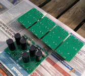
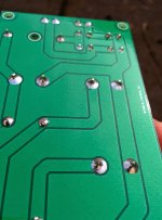
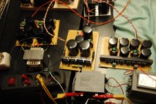
While I have your attention I want to show you my raw supply pics
😀
Thanks for the reply. My 801a is in the final stages. I've had to move out of the amp the raw filament dc supply and the power transformer.
So far though the 801A is better than anything I've had before (it's my first dht preamp)
And I ...can't help but think..mmmmm a later version...quieter?.... 🙂
I'm using V1.0 in my preamp. But I have some v4.0 as well...Sounds like a plan to put the v4 into the preamp. And the V1 for a 300b driver for the GM70 amp in my future.
Because the magnetic fields picked up by my plate chokes...I have not heard the preamp dead quiet yet. I'm sure if I have everything sorted I won't even feel the need to take out the v1's...
While I have your attention I want to show you my raw supply pics
😀
Attachments

I guess the question should be...is there a difference in the subjective listening experience? Between say a v1 and v7?
Excellent raw dc supply, Bas!
The overall character of the V1 and V7 are similar, but the V7 should usually give the best performance. I should not make too many great claims, but there are a few folks here who have compared.... maybe we will get some reports ?
The overall character of the V1 and V7 are similar, but the V7 should usually give the best performance. I should not make too many great claims, but there are a few folks here who have compared.... maybe we will get some reports ?
I'd think so, noting for one thing that before the primary appears the better balanced point to be implementing common mode mains filtering rather than closer to the filaments, and that grounding one filament terminal tends to make said more of a differential issue.Excellent raw dc supply, Bas!
Thanks for the input. I had to drop a little more voltage to get closer to the safe side...and thought reverse recovery spike function as well (not sure if that is an issue with schottkeys)noting for one thing that before the primary appears the better balanced point to be implementing common mode mains filtering rather than closer to the filaments
But do you think the resistors would be better on the primaries?
The resistors you have on the secondary side are already doing a very good job of reducing peak current as well as some filtering.
Common-mode chokes - when run well within current-rating - give some useful differential mode filtering, in most cases.
If you want to try the effect of more filtering, maybe a simple ferrite choke 0,33 - 1,0mH could be used after the first cap.
But I think that the regulator can already deal with any noise remaining after the raw dc supply you have now.
My own raw dc supply PCB is on the way now.
Think so too.But I think that the regulator can already deal with any noise remaining after the raw dc supply you have now.
About time. 😉 I had to have my own PCB manufactured...because I wanted it pretty. 😉 And ebay did not have what I wanted. Single supply...with optional dropping resistor(s).My own raw dc supply PCB is on the way now.
Attachments
Last edited:
Me too 😉I was lazy to make real PCB. 🙂
Some guy on a dutch forum drew it for me. Then I sent the files to China. And a week later I had the boards 😀
I don't have a heatsink because they get lukewarm...if that. Biggest heat is from the 1R dropping resistors. Since it is in a relative small enclosure I have drilled holes all over the thing...and got a 10dB 60mm fan to force air into the whole thing.
If I could work as neat as you do...I probably would not get pcbs's either for my raw heater supplies...

The v1 are not being replaced. My 801-A pre amp is so quiet... that I can't tell if it's switched on. [emoji2]. Unfortunately no comparison possible from other types of heating. Cause it's designed with the colemans from the get go. [emoji1]
Who am I fooling here? Always interested to go to the next level! And since no-one has volunteered to give a report. I guess I'll have to. Mail coming your way Rod.The v1 are not being replaced. My 801-A pre amp is so quiet
I've run out of MBR1045 Schottkies for my Sovtek 2A3's (2,5A heaters). The 1N5822 is listed for 3A max, would they endure the beating for the next couple of days? Getting luke warm within minutes...
Who am I fooling here? Always interested to go to the next level! And since no-one has volunteered to give a report. I guess I'll have to. Mail coming your way Rod.
Thanks Bas, I think you'll enjoy the latest version!
I've run out of MBR1045 Schottkies for my Sovtek 2A3's (2,5A heaters). The 1N5822 is listed for 3A max, would they endure the beating for the next couple of days? Getting luke warm within minutes...
Hi Jaap,
At 2,5A dc the rms current in both branches of the bridge-rectifier will be about 4,8A. So that's 2,4A per branch.
The 1N5822 can withstand an average current of 3A, but should be derated by 20% for capacitor loads - but it should be just about OK if the diodes are mounted on some PCB material, and well-ventilated.
If the case temperature of any diode exceeds about 80 deg C, add some kind of metal heatsinking (clipped in place)
Just got my 4P1L preamp going with RodC filament bias. Sounds great and so straight fwd, a big thanks Rod for the detailed instructions. Worked perfectly - with massive choke input raw supply.
It his has made me think about heater bias for IDH tubes. I have a phono 12B4a stage with 12v cathode bias. I can tie the cathode to the H+, using low noise voltage reg but then I know what the advice will be. Is there a difference in the interaction? ie a reason that makes a good voltage reg suitable for heater bias but not filament bias?
If not it calls into question any form of fixed bias, as they all are basically V=IR. And it may well be so. After years of fixed CLC bias SE amps I find cathode bias with poly caps is just plain better sounding. Maybe the RodC reg iswhat fixed bias supplies need. The current would be low so not that hard (not like filament bias). food for thought.
thanks again Rod, martin
- Home
- Amplifiers
- Tubes / Valves
- New DHT heater