hello John,
We can check the regulator is working correctly by measuring some test-points. Please send me some email & I can forward the set of points.
We can check the regulator is working correctly by measuring some test-points. Please send me some email & I can forward the set of points.
Hi Eduard,
thanks for adding info. Also I could add a note about the Q of filter you get with high choke inductance. There is an impotance of using several tens thousands uF capacitance to aboid voltage hill at the input of regulator at start. Also the high back voltage spikes on diodes occur same time.
I use min 33000uF, usually 3x22000uF and most important solution here is the use resistor in series with choke to press down the Q. With total resistance R+Rchoke=1,5 Ohms and 47mF capacitor the circuit charge time is on par with heating up time of regulator.
hello Alexei! Good to see you here.
With choke input, you can control the turn ON - turn-OFF voltage at the rectifier with a small Al-Polymer capacitor directly after the rectifier. The KEMET A750 series 470µF 25V is an example.
These caps are unusual - the ripple-current is at the Ampère-level, even at 47µF, and the ESR<20mΩ. They can withstand operation in this position.
I conclude the cap input might not be bad for this application, but it can pollute the line for for example the DAC, which can be sensitive, but I'm in the process of adapting a battery supply here.
The EM pollution into the mains is the biggest problem with capacitor input, and I believe it explains a lot of the improvement for choke-input. Direct measurement of the filament does not show any notable improvement with choke-input (Bela mentioned this, also) , since the regulator removes the ripple & noise.
Transformers for all parts of the DAC and digital sources can have an interwinding screen, to remove common-mode noise from the mains. This is how my DAC is fed (including a separate screened trafo and two layers of regulation for the oscillator)
Hello,
Thé famous Guido Tent told me to put a5 watt zenerdiode across the first cap to avoid the rising up to over voltage.
I also think that if you install a resistor that will take care there is always the minimum current needed to make it work properly.
Some time ago i had a problem with the Coleman. Two things solved the problem. This circuit needs a power tube with a cathode resistor.. And one of the circuits had a bad solder joint. Rod gave some voltages to check to determine where the problem is situated
Greetings, Eduard
Attachments
This circuit needs a power tube with a cathode resistor
No. I am using Coleman regulators with LED biased tubes and also in dc coupled amps with stacked supplies, cathode 0R grounded. No problems either way.
I think I'm doing something wrong with my Coleman Regs.
I got my problem sorted out. I ended up shielding the umbilical cable connecting the PSU with the signal chassis with some braided shielding tubing (tin plated copper).
This made a huge difference in my setup. All the residual hum vanished.
Many thanks to Rod Colman for kindly helping me eliminate other potential causes!
Regards,
John
Hello,
I think in general one could say that using better parts will allow you to put things closer to each other. I never had any problem with Lundahl chokes with that. Some open EI transformers need the AC meter trick to find the right orientation. Using the right choke will also lessen the influence from the transformer upon its surroundings.
Greetings, eduard
Hello,
Maybe i posted this one before but still could be interesting to members.
Article from a famous french engineer where you can see differences between choke and capacitor input when used to supply a 180 ma current.
On the left top choke input bottom cap input. On the right the current demand with choke input around 180 mA as requested by the load. With cap input switching between 180 and 425 mA. These peaks also occur in the transformer, diodes and the wires taking care of the connections. And this is only 180 mA most heater current are much higher.
So one more reason to use a decent choke input.
Greetings, Eduard
Attachments

Hi Rod and all, I just got the raw DC boards and populating them and ran into an issue. I'm using the TO220 rectifier diodes and don't know how they go on the board. I "assume" the taller mount tab go toward the back where the diode line is but that is just a guess.
Attachments
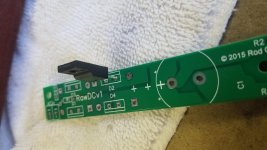
Your assumption is correct. That is the way you should put them into the board. Basically the line is the indication where the tab is that should connect to the heatsink.I "assume" the taller mount tab go toward the back where the diode line is but that is just a guess.
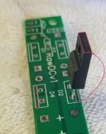
Assuming the diodes you are using have the same pin-out as ones that Rod recommends then the pic is the orientation.
I hope I'm answering the question you are asking !
Thank you for stepping in with the perfect answer!
Your assumption is correct. That is the way you should put them into the board. Basically the line is the indication where the tab is that should connect to the heatsink.
Thank you, Bas!
Hi Rod,
One of the things that I find *very* frustrating about this pursuit is the
lack of *any* presentation of any PSUD modeling of the power supply *AND*
the lack of any success with my own attempts to do so. I've been working
with PSUD II for at least ten, and probably more, years...mostly for HV
supplies and most of those cases have been successful. On this filament
reg supply, the only one I have gotten past the *driven negative for more
than X cycles within a Y time period*, was a choke input supply that did
produce a nominal 7.2V supply (for heating 45s), but it was with a 100V ???
transformer. 🙂 Go figure...and if you do, please, please let me know.
In PSUD, how to deal with the transformer output snubber? ...no clue.
How to deal with the R1s and R2s in the plus and minus rails...double the R
in the plus rail? ...no clue. What current to specify for the output?
...no clue. What am I missing...I'll be the first to admit to not knowing
something.
At this point, I figure for any success going forward I just have to build
it according to what you've provided...schematic, recommended transformer
for 45s, values for the rail resistors, and fire it up for a test with
dummy load resistors, and see what adjustment is possible.
Otherwise O.K.. 🙂
Best!
Robert
Using PSUD2 for Filament Supplies
Hi Robert,
The PSUD2 error driven negative for more than X cycles usually indicates that the loop impedance is too high, when feeding a current source.
I have (or can conjure) a PSUD2 file for almost any DHT Raw DC - please do ask if you need them.
I have attached a zipped up version for the 45, using a 6.3V rms 5A transformer.
With any DC rectified scheme, the rms current in the transformer is nearly 2x the DC current (the rms value is skewed by the high peaks of the rectifier-current pulses). These same pulses also mean that the transformer should be rated for power (VA) with 70% extra, to run cool & quiet.
In PSUD2, this is reflected in the low value (<200mΩ for 45) of the effective resistance of the transformer.
Capacitor Impedance: Similarly, representative values of large-electrolytic capacitor ESR values must be used in the PSUD2 model. You can start with 50mΩ by default. For more accuracy, check the data sheet for the exact part planned for the Raw DC supply, or measure them.
With high current supplies, careful choice of the rectifier type in PSUD2 is required. For DC output of 2.0A or less choose 1N5822 Schottky, to represent that same part. above 2A, where the real diode will be MBR1045, MBR1645, STPS1545 - choose 1N5828 in PSUD2, using the built-in standard types.
PSUD2 is not equipped to model the effect of the snubber. You can do it with PSPICE/LTPICE, but the snubber is there to modify the Q of the resonance(s) of the trafo's leakage-inductance with stray capacitances. It is better to work directly on the real supply, if you want to do some tuning. But the value supplied in the Raw DC are generally close for the recommended transformer types.
Attachments
Last edited:
Member
Joined 2009
Paid Member
for the most flexibility in SS simulations, use LTSpice. It’s free, comprehensive, widely supported on the forum, runs on both mac and pc. It requires more work and skill.
Using PSUD2 for Filament Supplies
Hi Rod,
Thank you - *Grazie Mille!* - for your reply and the .psu file for PSUD2 for the reg for 45s that I'm working on...it's really nice to put that into PSUD2, press Simulate and have an intelligible result pop up.
I have a few questions about your input values.
First, the rationale for the 440 mOhm in the + rail of the Pi filter...your Table 2.2 in the V8 for 45s shows 0.15 in both + and - rails...how to get to 440 mOhm in the + rail?
Second, re the 40 mOhm ESR for C1 and C2. I have a Dick Smith Mk II ESR meter...using it to check the ESR of the Nichicon 15000 uF 16V caps that I have sourced for this, the ESR is indicated to be 20 mOhm, so within reasonable distance...that gives a slightly higher V+ in PSUD2.
Third, the constant current sink value of 1.55A? And that leads me to the question: is a bleeder resistor desirable here...say for 50mA, the 0.05A beyond 1.5A?
Last, for the moment, I haven't looked into the transformer values for V and R, but I am using the Hammond 266L12 that you spec'd in Table 2.2.
And, I've got nothing on PSpice and LTSpice...Not an EE, if anything, I am a builder just trying to have some understanding guiding me along the way.
Thanks and Best,
Robert
Robert
Hi Robert,
To address you questions - which may occur to other constructors - I'll go through how I use PSUD2 for Fialemt Raw DC Supplies, step-by-step. I can highlight the answers to questions, as they appear.
Example: 45 DHT running with Hammond 266L12 Transformer.
The Hammond 266L12 is going to be used with secondary windings parallel, making it a 6.3V rms, 5A rms 31.5VA ac source.
We need to add the specs of the transformer, before we go further.
Open PSUD2. I will start exactly at the default setting, and default supply.
1. Double-Click on the Transformer. Press the ... (three dots button) next to the box Value - RMS V.
Add 6.3 to the V box, 5 to the A box. Regulation means the droop in voltage between the no-load and full-load condition. You can get this from the manufacturer, measure it, o just use a general estimate based on the VA of the trafo. Examples: for 10VA use 15-20%; 30VA use about 11%, 50VA 8-10%.
2. Select Diode type
Double-click the rectifier, select 1N5822 for 2A load (Like the 45 here) or 1N5828 for 2.5-6.5A loads.
3. Add RC Filter:
Hover over the Text: C filter.
Right-click → Change → RC Filter
4.
Hover over the Text: RC filter.
Right-click → Insert → C Filter
Now you have a CRC filter.
5. Add Parameters for C1
Double-Click C1.
for 45, Add Value: 15m (for 15000µF);
Add Resistance: 40m
This Resistance is the ESR of the capacitor. You can measure, or get it from the Data sheet.
But beware of entering an exact number: you measure 20mΩ, but this will increase as the capacitor ages; and we are liable to measurement errors at very low values. So I use 40m, to allow for a margin.
6. Add R1 Value.
In my suggested Raw DC circuits, R1 is composed of R2 and R3, which are just added to give a value for R1 in PSUD2. I used 440m in my example, as this is two 0.22Ω parts - use standard values, that you can actually buy.
7. Add C2 value.
Use the same procedure as for C1.
8. Load.
The Load is a constant current, and the results model best if PSUD2 is configured to suit.
Hover over the Text: Load.
Double-click the current load.
type in 1.55 for value 1. Then, press TAB to move to Value 2, press OK. This last manoevre prevents a stepped load from being created.
Why use 1.55A instead of the 1.5A from the Data sheet ? It is because this is a voltage specified filament. This applies to most DHTs, and means that the Voltage of 2.5V is a "Hard" parameter, and must be adhered to in the user's application. Long term, Vf must not deviate further than 5% away from the stated value, and preferably within -5% and +1%.
With Voltage-specified filaments, the stated value of current is a "Soft" parameter, and is only for guidance. it is usually close to its stated current, but it is not guaranteed. So using a slightly high value helps to check behaviour, if the sample filament is at that level.
9. Simulate and Tune
Now press Simulate, and click on C2's Box to see the output voltage.
you can adjust the output voltage by adjusting the value of R1.
As stated in the manual, having a few different values of R1 at han is a good idea, since they can be used to soak up variations in the transformer, line voltage, and filament.
While you are in PSUD2, look at the data columns to understand the component burdens:
I(T1) RMS column is the rms value of current in the secondary winding. the transformer should be run with 60-100% headroom, if cool and quiet operation is desired.
I(C1) → RMS column translates directly into the real-world Ripple-current burden for the Capacitor. Your chosen cap will have a value for Ripple current in the data sheet.
- Home
- Amplifiers
- Tubes / Valves
- New DHT heater