planet10 said:
We were posting simultaneously... impedance is unstuffed? The 3rd peak is indicative of significant ripple that should go away with some stuffing.
The shape of the saddle indicates you are getting some bass reiinforcement... with appropriate room placement to about 40 Hz.
dave
Is that a thumbs up? That's good because they are done except for crossover and finish.
My original had a simple series crossover, the details of which I can't remenber. One big cap 11uF and a coil that I'd taken a few turns off of. When I get time I'll measure the coil.
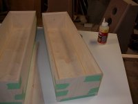
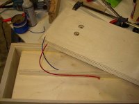
Construction details: 100% baltic birch plywood. Full mitered corners. This picture shows the box without it's back:
Attachments
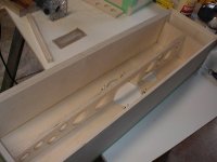
MJL21193 said:And here it is glued in:
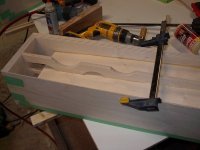
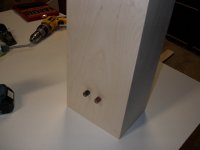
Did you put those braces dead centre? Looks like it, but i hope not cause it is too late to fix it.
Nice to see the holey brace propagating -- blessed by a bishop you know 🙂
dave
Whats wrong with dead centre? I eye-balled it, pretty close to centre. 😉planet10 said:
Did you put those braces dead centre? Looks like it, but i hope not cause it is too late to fix it.
Nice to see the holey brace propagating -- blessed by a bishop you know 🙂
dave
Here's the back, wires are glued to brace with hot melt. The two holes are the posts.
Attachments
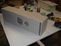
Very nice work there. Good fit and finish on those cutouts and edges- I wish I could get everything to come out so well.
joe carrow said:Very nice work there. Good fit and finish on those cutouts and edges- I wish I could get everything to come out so well.
Thanks Joe. Any thoughts on the crossover? I'd like to keep it simple. Like I said in the earlier post, I had a series crossover on the original, no zobel, no l-pad. I can't remember what freq I used or even how I designed it

MJL21193 said:Whats wrong with dead centre?
The centre of a panel is the worst possible place to put a brace. It clamps the panel such that the 1st (and most serious) vibrational mode (and harmonics) of the panel is more or less unaffected, and energy from other modes are shunted into it.
dave
Attachments
Further... to be most effective a brace should divide a panel into 2 dissimilar rectangles, even better, are braces that divide a panel into dissimilar trapezoids.
dave
dave
planet10 said:
The centre of a panel is the worst possible place to put a brace. It clamps the panel such that the 1st (and most serious) vibrational mode (and harmonics) of the panel is more or less unaffected, and energy from other modes are shunted into it.
Shifting it more to one side will fix it? I'll keep that for future reference. The panel is only 7" wide, with that brace, the span is a little more than 3". When I knock on this box it allmost sounds like it's made from 1" MDF. It's solid. I'm looking forward to a listen
🙂
planet10 said:Further... to be most effective a brace should divide a panel into 2 dissimilar rectangles, even better, are braces that divide a panel into dissimilar trapezoids.
dave
I actually thought about putting it on an angle, breakup more standing waves, then I said to myself the holes will do that. Next time.
MJL21193 said:Shifting it more to one side will fix it?
Yes... i'm often using it as a driver brace, and often the driver finds itself centered, so i put one edge of the brace at the centre line. When i have more latitude i'll use root(2) or the golden ratio.
dave
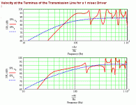
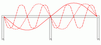
MJL21193 said:I simulated the original with Martin King's model to see the difference. The old one is on the top, the new on is on the bottom. I think this is a difference that you can hear.
Yes. Goes lower, with less ripple.
dave
I remember now that I used a spreadsheet from http://www.speakerbuilder.net/web_files/Articles/perkinsxo.htm
to design the old crossover. The link on the page is not working now. It was for "Andy's adjustable spreadsheet".
I'm thinking someone out there knows where it went or at least could point me towards another one.
Anyone?
to design the old crossover. The link on the page is not working now. It was for "Andy's adjustable spreadsheet".
I'm thinking someone out there knows where it went or at least could point me towards another one.
Anyone?
MJL21193 said:It was for "Andy's adjustable spreadsheet".
http://users.tpg.com.au/users/gradds/
dave
Thanks Dave.
Playing with the spreadsheet tells me My original was crossed at 2500Hz with a zeta of .8. This is probably too low. I think the tweeter will be more comfortable at around 3500Hz.
The woofer has good responce all the way up to 5000 Hz, the tweeter looks best in the 3000 to 4000 range.
Given the woofer is a poly cone, will I hit break-up if I crosss higher? Say as high as 4000?
Any help in this would be appreciated.
- Status
- Not open for further replies.
- Home
- Loudspeakers
- Multi-Way
- New Compact TL Project