Hi,
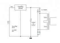
add in an RCRC supply to the Cetoole shunt reg when when using >20Vac to feed a regulated 18Vdc.
There is more than sufficient voltage overhead to allow Vdrop across the Rs.
I'd suggest the first RC is 10r + 2200uF, the second could be separate 10R + 1000uF to each regulator.
4 regulators each drawing 70mA would require >=15VA 24Vac to give 4 times 40mA to load @ 18Vdc.
If the transformer is available, then Vac = regulated Vdc when using a simple rC supply.
Hi,
I know the advantage of CRC or RCRC with respect to the ripple voltage. No doubt.
Nevertheless, I'd like to hear from you about one thing. I wonder whether the CRC or RCRC still has any real value to be considered in front of the "voltage regulator of good quality". My question is further boosted whenever I think of light loads of low current. Is there still any real value of CRC or CLC? Or, it is just a kind of hazy expectation?
Kindly bear my ignorance . . .
Cheers,
🙂
Babowana said:Hi,
I know the advantage of CRC or RCRC with respect to the ripple voltage. No doubt.
Nevertheless, I'd like to hear from you about one thing. I wonder whether the CRC or RCRC still has any real value to be considered in front of the "voltage regulator of good quality". My question is further boosted whenever I think of light loads of low current. Is there still any real value of CRC or CLC? Or, it is just a kind of hazy expectation?
Kindly bear my ignorance . . .
Cheers,
🙂
The reason for suggesting a CRC, was mainly to get rid of a little of that extra voltage, which is not really needed, and in the process clean up the supply a bit.
The reason for using a CLC like I did in the ones I built, is to counter the Toolereg's dropping noise rejection at higher frequencies. A small inductor at around 22-47Uh is a good shot at removing that high frequency noise, before it enters the Toolereg. Not sure if you can detect the difference in practical use, though😉 The simple supply you posted will probably work just fine, but the inductors are easy to wind yourself, if you wanted to.
Another note: It is best to remove the CRC supply filter that you have in the B1, before connecting the Toolereg. Keeping them, will ruin some of the shuntregs performance, Mainly by destroying the regs flat output impedance, A 10uF filmcap is about right for C2, with no electrolytics to follow. If you still want local decoupling in the B1, then use filmcaps.
One more thing. When you have soldered everything and have it up and running you can calculate the excact current through the CCS: (Vled-Vbe)R6=mA Vled is the forward voltage of D1, and Vbe is base-emitter voltage of Q5. The values must be measured in the actual circuit, to be precise.
🙂
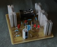
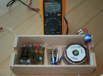
Babowana said:My first experience with toolereg is goind well (see the circuit in post#79). Now I'm cutting a board to fabricate the simple filter as shown in post #81 . . .
Cheers,
>>🙂<<
Looks great.... Good luck on firing up 😉
🙂

I'm doing test of the toolereg with no loading.
Unregulated input voltage is 30V.
Regulated output voltage is measured to 2.6V. ???
Red LED D1 is on, but D2 is off. ???
I have replaced suspicious elements, i.e. D2, Zener, Q3, Q4, Q6 and Q7 . . . but, the result is the same as above.
What's wrong (referring to the schematic in post#79)?
>>>>> <<<<<
<<<<<
Unregulated input voltage is 30V.
Regulated output voltage is measured to 2.6V. ???
Red LED D1 is on, but D2 is off. ???
I have replaced suspicious elements, i.e. D2, Zener, Q3, Q4, Q6 and Q7 . . . but, the result is the same as above.
What's wrong (referring to the schematic in post#79)?
>>>>>
<<<<<Attachments
Hi Babo. What is the value of the 5 stacked resistors (R6)? If the value is too high; the CCS cant source enough current and the LED will not light up. You can probably use fewer resistors, since they doesnt get very hot. Try with 22r for R6 and load the outptut with approx 2k 1-3 watter resistor.
🙂
Edit If the above doesnt work, try to turn D2, 180 degrees.
🙂
Edit If the above doesnt work, try to turn D2, 180 degrees.
R6 is 20 ohms as five 100-ohm Rs are paralleled.
I'm 100% sure that D2 sees the right direction.
I have increased R8 to 360 ohms. No cure . . .
I will re-try with a 1.5K-2K load.
Cheers,
>>🙂<<
I'm 100% sure that D2 sees the right direction.
I have increased R8 to 360 ohms. No cure . . .
I will re-try with a 1.5K-2K load.
Cheers,
>>🙂<<
Did you use a trimpot for R4 or R15? If not, try that first. You can use a trimpot in both positions, but its best to replace R15.
🙂
BTW the two LED's are pointing in opposite directions on the board. Katodes pointing towards each other.
It looks like Q3 is facing the wrong way on your board. Could you post a pic taken directly from the top?
OBS Edited!
🙂
BTW the two LED's are pointing in opposite directions on the board. Katodes pointing towards each other.
It looks like Q3 is facing the wrong way on your board. Could you post a pic taken directly from the top?
OBS Edited!
I have tried with 2.2K (2W) load, with no success.
The red LEDs are back-to-back in direction on board surely as you said.
Before I do anything with R4 and R15, I am wondering why I don't get the reference voltage at the emitter of Q3.
Cheers,
🙂
PS. For your info, I'm using KSA733Y for Q1, Q4 and Q7 replacing BC556C . . .
When I turn off the power, D1 goes off and D2 on very briefly and both off . . .
I just edited my last post regarding Q3. Not sure though, its hard totell from the pic. Is Q3 a BC546?
That ought to work. Do you have a 12V zener to try? (Or a combo to get 12V)
Also check the raw supply with your meter for correct polarity. Positive goes to the pad nearest C4.
🙂
Edited.
Also check the raw supply with your meter for correct polarity. Positive goes to the pad nearest C4.
🙂
Edited.
I believe that I didn't make any error with the things I can check and see with my eyes. The error must be inside where the electrons are involved in . . .
I have 3 x 4.3V zeners. I wonder if this replacement will solve the problem . . . I will try it tomorrow . . .
Cheers,
🙂
I have 3 x 4.3V zeners. I wonder if this replacement will solve the problem . . . I will try it tomorrow . . .
Cheers,
🙂
Attachments

Usually, when I had an issue like yours, it was for one of two reasons. 1) the CCS is sourcing too little current or, 2) one of the LED's is turning the wrong way.
I mainly suggested to look at the zener just in case it is fried or something. I use 12V zeners in mine and that works fine.
🙂
I mainly suggested to look at the zener just in case it is fried or something. I use 12V zeners in mine and that works fine.
🙂
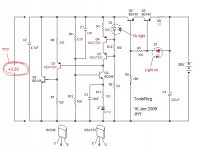
I have once again changed Q1, Q3, Q4 and Q7 with new, being careful not to introduce too much heat to them during soldering. I have also changed D2 with new, being careful for the forward biasing of the red LED. And, I have changed Z with new. I have played with different values of R1, R3, R6 and R8 . . . (see the attachment showing latest values) . . .
All means give me no cure . . . 😕
Yeah . . right, I have one spare board 😉
When I have better time, I will have another chance to try to make a complete new regulation board on the spare one . . . First, I will pray for my luck . . .
Cheers,
>>🙂<<
All means give me no cure . . . 😕
Yeah . . right, I have one spare board 😉
When I have better time, I will have another chance to try to make a complete new regulation board on the spare one . . . First, I will pray for my luck . . .
Cheers,
>>🙂<<
Attachments
- Status
- Not open for further replies.
- Home
- Amplifiers
- Pass Labs
- New-building of my B1 buffer