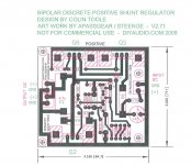
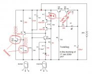
Did you check about Q5 and Q6? They are the only ones left (with Q2) that can be the cause. I assume that you did check all the tracks for solderbridges and scratches. A thin scratch can cut a track, and be hard to detect. Check the board carefully on the track side, with a magnifierglass. I have attached the latest component placement for the positive reg, and am sorry that it doesnt work yet. (R9 is deleted, and simply left out)
🙂
🙂
Attachments
Weird case. All of mine works, no doubt, but I am starting to run out of good ideas. Maybe its time for some weird ideas.
1) Try to lift one end of the output cap and see if that changes anything. I have seen those MKP's do weird things.
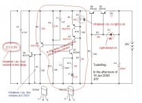
2) Try to apply a little voltage to the LED's to double check their polarity. (I know I repeat talking about the LED's😉 ) Maybe a battery will do. D1's positive leg goes to R6/C4 and D2's positive leg goes to Q6.
3) The only part that differs from mine is the KSA733's, but I think they should work anyway. I can send you some BC556c's if you want them?
🙂
1) Try to lift one end of the output cap and see if that changes anything. I have seen those MKP's do weird things.
2) Try to apply a little voltage to the LED's to double check their polarity. (I know I repeat talking about the LED's😉 ) Maybe a battery will do. D1's positive leg goes to R6/C4 and D2's positive leg goes to Q6.
3) The only part that differs from mine is the KSA733's, but I think they should work anyway. I can send you some BC556c's if you want them?
🙂
no.steenoe said:
2) Try to apply a little voltage to the LED's to double check their polarity. (I know I repeat talking about the LED's😉 ) Maybe a battery will do. D1's positive leg goes to R6/C4 and D2's positive leg goes to Q6.
The LEDs should be forward biased. The +ve goes to the negative voltage side not the positive voltage side.
I think of the anode side, as the positive leg on LED's. Anyway, i just spotted that the small "A"'s on the component layout are wrong, thanks to what you said, Andrew. The anode side still goes to the connections I mentioned.
JH, you might want to try and turn the LED's around.
🙂
JH, you might want to try and turn the LED's around.
🙂
I understand the symbol of diode, and Anode (p-region side) and Cathode (n-region side). I also understand how it should be foward biased. The anode is to be positive with respect to the cathode. LED has two legs. In general, slightly longer leg is the anode (say + to be connected) while shorter one is the cathde (say - to be connected). Trust me. My LEDs are correctly connected 😉
I have removed the output cap (4.7uF). No cure . . .
I think I could find BC556 near hear. Anyhow, thank you very much, Steen, for your kind offer . . . 🙂 If I think of your kindness, I have to find out what my error is and have to show you a good result . . . . . .
. . .
Cheers,
>>🙂<<
I have removed the output cap (4.7uF). No cure . . .
I think I could find BC556 near hear. Anyhow, thank you very much, Steen, for your kind offer . . . 🙂 If I think of your kindness, I have to find out what my error is and have to show you a good result . . .
. . .Cheers,
>>🙂<<
Ah . . . by the way . . .
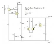
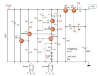
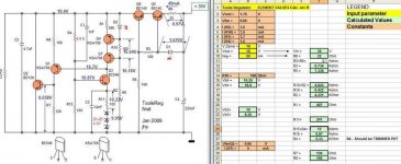
After Toolereg project, I'm going to start another shunt regulator as shown here. The Toolereg is however pulling my leg . . .
In the attached circuit, I'm trying to have a current limiter, reference voltage, sampling circuit, error detector, control element and slow start. I'm applying Papa's diy op amp for the error detector and the control element.
Do you have any opinion, advice, recommendation or criticism?
Do you think it's better for me to open a new thread?
Cheers,
>>🙂<<
Attachments
Back to Toolereg . . .
Just to see reaction, I have connected the unregulated 30V as shown.
I have immediately removed the power from the wall socket.
Hmm . . . I want to build Toolereg from scratch once again. I will start it now. As I have spent all KSA733, this time I'm goint to use KSA708 instead of BC556.
Cheers,
>>🙂<<
Just to see reaction, I have connected the unregulated 30V as shown.
- D2 light on but soon off
- Q2 smoked
- Then R7 smoked too
I have immediately removed the power from the wall socket.
Hmm . . . I want to build Toolereg from scratch once again. I will start it now. As I have spent all KSA733, this time I'm goint to use KSA708 instead of BC556.
Cheers,
>>🙂<<
Attachments
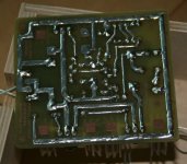
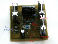
I have just finished the second board.
I have done my best to avoid mistakes.
I have checked polarities of D1 and D2 very carefully.
I have replaced 1 x 9.1V zener with 3 x 4.3V zeners.
Accordingly, R4 has been changed from 8.2K to 3.6K.
Attached is the photo of the second board.
Cheers,
>>🙂<<
I have done my best to avoid mistakes.
I have checked polarities of D1 and D2 very carefully.
I have replaced 1 x 9.1V zener with 3 x 4.3V zeners.
Accordingly, R4 has been changed from 8.2K to 3.6K.
Attached is the photo of the second board.
Cheers,
>>🙂<<
Attachments

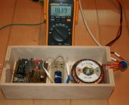
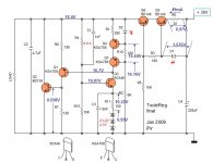
Here are voltage measurements.
I have no idea why I get only 9.95 volts from the three 4.3V zener stack--probably too low zener current . . . ? So, I get the reference voltage of 10.87 volts at the base of BC546. Accordingly, I have changed R4 value to 6.8K. Now I get the regulated voltage of 18.4V.
THANKS, STEEN!
Cheers,
>>🙂<<
I have no idea why I get only 9.95 volts from the three 4.3V zener stack--probably too low zener current . . . ? So, I get the reference voltage of 10.87 volts at the base of BC546. Accordingly, I have changed R4 value to 6.8K. Now I get the regulated voltage of 18.4V.
THANKS, STEEN!
Cheers,
>>🙂<<
Attachments

Babowana said:Here are voltage measurements.
I have no idea why I get only 9.95 volts from the three 4.3V zener stack--probably too low zener current . . . ?
Yes - low current - If You want to play around a bit, You could try to lower R1 a bit (300 -330 Ohm...)

spavleski said:
..., You could try to lower R1 a bit (300 -330 Ohm...)
Thanks for your tip. I will keep it in mind.
Cheers,
>>🙂<<

- Status
- Not open for further replies.
- Home
- Amplifiers
- Pass Labs
- New-building of my B1 buffer