R6 has about 1V across it. Why the need to specify 1W when dissipation is ~50mW?
R5 has been discussed at length. Change it!!!!
R5 has been discussed at length. Change it!!!!
AndrewT said:
Change it!!!!
Soft tone!!!!!!!
My ears still ok 😉
I have just wanted to glue myself on the original as I have received. Is this wrong . . . ?
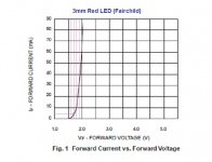
I have no idea about the actual relation between the forward current and the forward voltage of the red LED. Do you have any? Please give it to me. Then, I could choose proper R6 and R5 myself.
So, which values you recommend? Give me technical explanation instead of the meaningless "!!!!!!" . . .

Ah . . . Thank you, Mike.
The drawing and Tony's note are new to me.
I will read through these.
Thanks again.
>>🙂<<
The drawing and Tony's note are new to me.
I will read through these.
Thanks again.
>>🙂<<
My bad, i just send a schematic that was lying on the table I forgot about R5 that was changed to 10k. The latest changes to the Toolreg took place in the GB thread, and it seems that You (that is JH You😉 ) Didnt follow that particular thread. Here is a link to the thread, it might be worth reading through it: Toolereg GB
Regarding R6 I suggest a somewhat higher value. Around 25-27r is probably as good as any, allowing for some excess current flowing through the shunt. The final value should optimally be as low, as your heatsinking of Q2 allows for.
In any case, I hope you will have some fun with the Toolereg😎
🙂
I forgot about R5 that was changed to 10k. The latest changes to the Toolreg took place in the GB thread, and it seems that You (that is JH You😉 ) Didnt follow that particular thread. Here is a link to the thread, it might be worth reading through it: Toolereg GB Regarding R6 I suggest a somewhat higher value. Around 25-27r is probably as good as any, allowing for some excess current flowing through the shunt. The final value should optimally be as low, as your heatsinking of Q2 allows for.
In any case, I hope you will have some fun with the Toolereg😎
🙂
steenoe said:
The final value should optimally be as low, as your heatsinking of Q2 allows for.
😎
🙂
Steenoe,
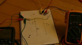
It looked like from a picture I saw (and maybe I was having a moment) that you had the BC1xx attached to the bottom of the case. Sort of sans heatsink. Am I to assume that with a 30v input, for something like NS-10, we will want a bigger chunk of something?
mithomas said:
Steenoe,
It looked like from a picture I saw (and maybe I was having a moment) that you had the BC1xx attached to the bottom of the case. Sort of sans heatsink. Am I to assume that with a 30v input, for something like NS-10, we will want a bigger chunk of something?
This is what you must be referring to:
Compact Toolereg
That is the compact version, designed for being attached to a chassis, somewhere convenient. I simply bolted it to a piece of heatsink for testing purposes and you can easily use something much smaller for a NS10. It is generally accepted though, that a shuntreg performes better with more current through it, so go ahead and go overboard if you like😉 For a NS10 (or B1) it will be perfectly fine to bolt the Compact version to the chassis. There is no need for additional heatsinks.
It is not easy to take that approach with the board that Babowana has, since the BD1xx's are turning the wrong way for that! It will be easier to use some small heatsinks, mounted onboard.
🙂
steenoe said:
...
In any case, I hope you will have some fun with the Toolereg😎
🙂
Sure, I will 🙂
I could not follow the other thread.
I have lack of active time, waiting for my hair growing up newly very slowly . . .
I will try to read thru . . .
Thanks, Steen.
>>🙂<<
Hi,
your red LEDs are likely to drop 1.5V to 1.6V at the normal 2mA to 5mA that is commonly used.
your red LEDs are likely to drop 1.5V to 1.6V at the normal 2mA to 5mA that is commonly used.
AndrewT said:Hi,
your red LEDs are likely to drop 1.5V to 1.6V at the normal 2mA to 5mA that is commonly used.
Thanks for kind info, Andrew.
Who will stop me . . . ?
I had a simple test with two red LEDs. According to the test, the red LED met about 1.7V drop on about 3.5mA current. I will go with this 3.5mA for my test of TooleReg . . .
Cheers,
>>🙂<<
Attachments
Hairr-Babo,
very few LED datasheets show an accurate If/Vf graph in the 0-10mA range. (e.g. a high efficiency 5mm LTL-307)
A LED still is a semiconductor, measuring the range yourself is the only way to find out.
Stuff like J309 or BF245 are pretty cheap, considered a 3-piece J-CCSuit ?
very few LED datasheets show an accurate If/Vf graph in the 0-10mA range. (e.g. a high efficiency 5mm LTL-307)
A LED still is a semiconductor, measuring the range yourself is the only way to find out.
Stuff like J309 or BF245 are pretty cheap, considered a 3-piece J-CCSuit ?
I like your reg, Salas 🙂
One day, I will give it a try.
By the way, any one measured voltage across R8 of Toolereg?
Do you have any figure? Thanks.
Cheers,
>>🙂<<
One day, I will give it a try.
By the way, any one measured voltage across R8 of Toolereg?
Do you have any figure? Thanks.
Cheers,
>>🙂<<
Babowana said:voltage across R8 of Toolereg
Mr Samson You still needs to grow a few more hairs.
=> Vbe of Q2, R7, R8.
jacco vermeulen said:
... still needs to grow a few more hairs.
=> Vbe of Q2, R7, R8.
Igoo, igoo . . .
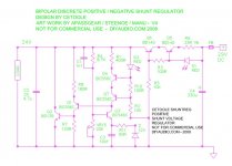
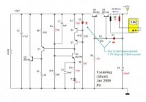
You are absolutely right. More hairs, which I need . . .Thanks to your and friends' advices, I sum up my toolereg as shown, hoping this will work fine. The unregulated input voltage of +42V and red-marked resistors are considered because I want to utilize things in my pockets. Any further advice?
Cheers,
>>🙂<<
Attachments

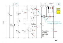
Babowana said:My poor head . . .
I have a smaller secondary transformer 2x12Vac (50VA).
Retouching the values . . .
Cheers,
That should work just fine. What do you have in mind for the raw supply? If you do a CRC, a volt or two could be dropped there, cleaning up the supply a bit at the same time.
🙂
- Status
- Not open for further replies.
- Home
- Amplifiers
- Pass Labs
- New-building of my B1 buffer