jReave,
Do you have the FRD & ZMA files for both the XT25TG30-04 & 830875 that you would care to share?
Cheers,
David
Do you have the FRD & ZMA files for both the XT25TG30-04 & 830875 that you would care to share?
Cheers,
David
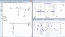
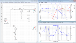
Attached. Including drivers with baffle diffraction and the XSim file too.
Don't forget to change the file type from .txt back to .frd or .zma
Don't forget to change the file type from .txt back to .frd or .zma
Attachments
-
Peerless 830875 + Vifa XT25TG30-4 (rough).dxo81.1 KB · Views: 78
-
raw FR spec sht XT25TG30-4.txt22.4 KB · Views: 64
-
FR Prls 830875 on 8x14in bfl at 4x5.5in r=.5 d=3ft -5d vertical.txt13 KB · Views: 59
-
raw Z spec sht Prls 830875.txt22.9 KB · Views: 61
-
raw FR spec sht Prls 830875.txt19.5 KB · Views: 43
-
FR XT25 on 8x14in bfl at 4x11in r=.5in d=3ft on-axis.txt12.9 KB · Views: 55
-
raw Z spec sht XT25TG30-4.txt23.5 KB · Views: 56
WOW!!!! TY sir!!!
I will learn how to get these loaded and start playing with the sim while waiting for the other parts to arrive.
I have read that baffle diffraction and proper phase should be included with the simulator plots. I do see the BD included and does that include phase as well?
These should work out well considering my baffle is the same size as that indicated on the file names. BONUS!!!
Again, thank you so much for the help.
Cheers,
David
If you measure the response in the cabinet baffle diffraction is included by default as it's part of the frequency response.
Phase response is included as a separate column in frd files. For appropriate relative phase response measurement between drive units you should ensure that 'time zero' is the same when each unit is measured. I find this best acheived by measuring tweeter first with time zero set automatically, then using that time zero setting for subsequent measurements of any the other units.
Phase response is included as a separate column in frd files. For appropriate relative phase response measurement between drive units you should ensure that 'time zero' is the same when each unit is measured. I find this best acheived by measuring tweeter first with time zero set automatically, then using that time zero setting for subsequent measurements of any the other units.
That works for measured data. For the manipulated spec sheet data, you can derive the phase mathematically as a function of the FR. XSim can do it in the Tune window - choose "derived" instead of "measured".
But the files are already loaded into XSim with phased derived, relative acoustic centers added ("mod delay" on the woofer) and BD included too. The only thing I didn't do was add in the box effects to the woofer FR and impedance but it won't matter much in this instance. Or in other words, I got lazy. 😀
But the files are already loaded into XSim with phased derived, relative acoustic centers added ("mod delay" on the woofer) and BD included too. The only thing I didn't do was add in the box effects to the woofer FR and impedance but it won't matter much in this instance. Or in other words, I got lazy. 😀
Thank you both for your replies.
TOTAL XO software nubby here!!!!
This may be a silly question but..........does the .dxo file contain all of the individual files that are listed? If it does not, which files should be saved as .frd and which .zma? I assumed that the FR plots would be saved as .frd and the impedance plots as .zma. Is this correct?
Cheers,
David
I have opened the .dxo file in Xsim and it appears to be something. What I mean by that is......... I need to dig into the software and understand what is in front of me on the screen and how it all works. Kind of lost right now and I do not expect anyone to do the work for me so off to research and study.
The help section leaves a bit to be desired. I did find a video and hope that helps along the way.
Cheers Gentleman!!
The help section leaves a bit to be desired. I did find a video and hope that helps along the way.
Cheers Gentleman!!
Ok great!!! The video helped immensely. Now I know "roughly" what I am looking at, where to manipulate the parts and drivers and what I can expect to see. This seems like a very useful tool.
So jReave...........you did all of that work initially and for that I am truly grateful.
Here is to learning and contributing!!!!
Cheers,
David
So jReave...........you did all of that work initially and for that I am truly grateful.
Here is to learning and contributing!!!!
Cheers,
David
I picked up a DATS V3 from PE so I can measure the actual drivers I am working with. I suspended the drivers from the rafters with a coat hanger in my basement lab about half-way down toward the floor. I have a rather traditional lab with normal shelving and lab type gear. I made sure there was a MIN of 2ft between ANY boundaries and I am getting very out of tolerance measurements in free space on the 830875 units. The data sheet tells me I should be at 46Hz (+/- 15%) for Fs and I am consistently getting 66.7Hz and 63.6Hz on the two drivers with DATS.
One question though............is there a way to counteract ambient room noise in the software? I have loud fans in some of the equipment and it may be contributing to the out of spec readings? Is there something wrong with my process? Do I need a different environment to measure them?
Cheers,
David
If they are unused you probably need to break them in before measurement. Fs will probably drop significantly after running a low frequency sine wave through them for a while.
Last edited:
I suspended the drivers from the rafters with a coat hanger in my basement lab about half-way down toward the floor.
That should work well for impedance and T/S measurements with DATS V3. I found that DATS is so sensitive in impedance measurements, it can detect a nearby reflective surface (like a wall 20 inches away) and give you a "wiggle" on the impedance curve. It is a very good instrument.
Measuring suspended as you are doing is considered "best practices"
I agree with TimA. Run a 20 to 25 hz sine wave through the drivers. I have used 2V RMS in the past on small woofers and it works fine.
Last edited:
Hmmmmm...........now the real problem is the computer I use for ALL of my DIY Audio stuff is the one with the noisy fans. UGH!!! Gonna have to think through this one.
IIRC the enclosures are sealed and already built? If so I personnally wouldn't worry about accurate measurements of the T/S parameters as long as you know the internal volume is about right as it won't make much difference anyway. If the enclosures were ported that WOULD necessitate accurate measurements.
For this project alone yes, the enclosures are finished and not vented. I was just trying to get acquainted with the new tool and how to use it properly. I will need to find a way to minimize that noise on any future project though. Maybe I could just use a windows laptop to gather the data then transfer it to the main machine after the measurements are complete.
d
d
Ok so this may seem obvious to some and I hope it is.........with this circuit:

What load is the amp seeing if BOTH of these drivers were 4ohm?
Cheers,
David
What load is the amp seeing if BOTH of these drivers were 4ohm?
Cheers,
David
Without driver specs, particularly the woofer impedance curve showing a rise in impedance as frequency increases due to inductance, it's impossible to say but probably not much less than 4 ohms anywhere. Best guess is minimum of 3 ohms at a few hundred hertz. Nearer 4 ohms in the top octaves unless the woofer has low Le (inductance).
Tim,
Thank you sir!! I was just checking since I had both 4ohm drivers installed (before swapping in the 8ohm woofer version). While running it in 4ohm mode on my amp and as I increased the volume a bit, the amp went into "protect" mode and shut down. It is a new amp and I was hoping I did not jack it up or the drivers for that matter.
Getting back into this DIY Audio thing after so many years away..........so much has changed regards amp technology, HDMI interaction and auto room correcting software. When I first started using the amp it would turn on for a few mins and back off again, seemingly all on its own. It took me a week to research that it was because the TV would perform an update in the background while the TV actually appeared to be turned off and the HDMI cable was telling the amp to wake up.
- Home
- Loudspeakers
- Multi-Way
- New Build.......XT25 & 830875