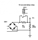
I'm also a fan of the cap multiplier for ramping up the power supply voltage slowly, but it doesn't help with the voltage on the cap after the rectifier.
The voltage after the rectifier is good. Just the ones in the amp are stressed for a few seconds... I'm considering just using a 6Z4 in series with it. If I run it from 12V and use a 10R resistor for the heater, the ramp up should be pretty slow.
I'm just not looking forward to ripping everything down from the rack again...
I'm just not looking forward to ripping everything down from the rack again...
Ah, I assumed you were talking about the power supply; so you mean the 47uF bypass caps? Are they film caps? They might be more tolerant of overload anyway. I think I'd use zeners rather than go to the trouble of a thermionic diode.
Edit; I see they are electrolytic.
Edit; I see they are electrolytic.
Nope.. The quadupler can put out 700V with no load, and the PSU caps can handle 900V, but the in circuit power filtering caps are only rated to 600V. They are electros. https://canada.newark.com/epcos/b43541b8476m000/cap-47-f-600v-alu-elec-snap-in/dp/16AC3106
So either I make a zener string, or use a soft start (or put a big load resistor on it).
So either I make a zener string, or use a soft start (or put a big load resistor on it).
Wow... According to TDK's useful life calculator the caps near the power stage will last about 25000H, and the ones in the line section will last 238000H!
Also. The 6N24P can be used as a CF without the microphonic noise developed in a grounded cathode gain stage.
Next time I use one, I'll invert the triodes and see if that makes a difference.
Next time I use one, I'll invert the triodes and see if that makes a difference.
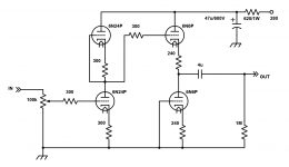
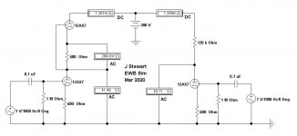
The active loading looks like the following. The first top triode and second bottom triode could be replaced by resistors or CCS like 10M45 from IXYS...
The autobiasing is done with an AB-4 from Pavel -> Module AB-4 for 4 tubes, PP & PPP amps, requires 6.3VAC & bias supply from the amps circuit, with TTL error signal output. TES
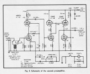
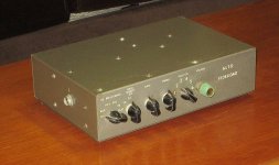
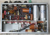
Here is what you are calling 'active loading'. This one built around 1956 while I worked at Ferranti R&D. The original cct was published in Audio Magazine about that time. The front end is simply a cascode connexion. The noise is down in the microvolts.
Still here on the shelf, hasn't run in years.🙂
Attachments
Amazing! I mean it's similar anyway. Mine has no feedback loop etc and it's certainly not cascode...
What I call "Active loading" is effectively using the second triode in the envelope instead of a resistor. Better performance than the resistor. In this case like a constant current sink/source, and most of the waste heat it radiated above the chassis. Plus the distortion curve supposedly cancels.
What I call "Active loading" is effectively using the second triode in the envelope instead of a resistor. Better performance than the resistor. In this case like a constant current sink/source, and most of the waste heat it radiated above the chassis. Plus the distortion curve supposedly cancels.
Last edited:
Link to the complete article in Audio magazine-
AUDIO - Consumer audio and music magazine from 1947 to 2000.
Click on 1955 October, starts on p23.
The first stage is a cascode, used for low noise but gain like a pentode without pentode noise. Triodes have less noise than pentodes, no separation of cathode current by a screen on the way to the plate.
The 2nd stage is a mu follower, low D% since the top triode looks like a current source load. The 3rd stage is not quite a White CF, the bottom triode is not driven by the top. But response is good for both +ve & -ve going transitions, something an ordinary CF does not do.😱
Read all about these three stacked triode configurations in old EE text books.🙂
jhstewart9, 2nd stage is not what I think of as a mu follower (lower anode AC coupled to upper grid, output from upper cathode); which old textbook has an analysis of this stage?
Actually, the output is from the lower plate... This is now 6N1P, not 6N24P. No circuit changes were required other than termination of 100k instead of 1M.
Attachments
Last edited:
Koda, I was referring to the second stage of the schematic in post 87 not being a mu follower (as I understand them).
jhstewart9, 2nd stage is not what I think of as a mu follower (lower anode AC coupled to upper grid, output from upper cathode); which old textbook has an analysis of this stage?
It is deceiving, the 2nd stage is a minimal mu follower. We would usually see in addition to the 680R biasing resister another resister is series connected to the bottom plate. And then a cap back up to the top grid.
The cct in the 2nd stage has a 680R between the grid & cathode so the upper tube looks like a load of {(mu + 1)*680 + rp}. The 680R cathode resister about doubles the load as seen by the lower tube.
So stuffing the numbers taken from the RCA data sheet into your HP, TI or Casio calculator & turning the crank we get
{(100 + 1)*680 + 62500}R or 131.18 K. Looks like the top tube is an active load, not passive.🙂
Otherwise the load would simply be rp, 62.5K, its not.
Books you should have in your library as follows-
Radiotron Designers Handbook, Ed 4 (often referred to as RDH4)
Electronic & Radio Engineering, Fred Terman, Ed 4
Valve Amplifiers, Morgan Jones has a good workup on a mu follower.
Many of the classic texts of the tube era are now shewing up for sale on the iNet from the estates of Geezers like me as we expire.😀
I learned my stuff as the art transitioned from tubes to Ge & Si semis. And spent 10 yrs in R&D.
Thank you, I follow this, but what is the advantage of using a tube rather than a 170k resistor in this case? I have all three of these books but I only remember Jones covering these compound stages to any great extent. Valley and Wallman is more comprehensive, but I really have to be in the mood to dive into that!
My copy of Morgan Jones book published 1995 has a workup on the mu follower beginning on p94, very informative. I believe there is a more recent Jones book.
I've also got a copy of Valley & Wallman, a useful reference as well. But not as good for audio as either Terman or RDH4.
The White CF has been around since the 30s, should be lots on the iNet, Same for the Cascode connexion. Lots on Noise Figures of tubes & various connexions in both RDH4 & Terman. Many other books on EE & audio are useful.
Much audio information in copies of Audio & other magazines that are referenced in the link posted earlier. Includes amps, preamps, disc. tape, receivers & on & on. All free for the taking at no cost.
Just need to look for all, its out there!🙂
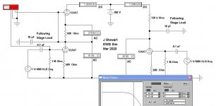
Frequency Response Comparison
The cct vers using the active load is marginally better than the vers using a simple resistor load. The 10 pF load is arbitrary but in any case very low since it goes to the grid of a CF. Rest might be stray C in the wiring.🙂
So in this example the R load is down 3db @ 207 KHz
while the active load vers is down 3db @ 265 KHz.
Either would be OK.
Attachments

Thank you for going to the trouble of doing this. Maybe they just couldn't bear to leave half the triode unused (mono unit if 1956).
- Home
- Amplifiers
- Tubes / Valves
- New build: 36LW6 integrated amp with phono avec SMPS/DC Boost.