Member
Joined 2002
BrianDonegan said:I think there were a lot of surplus-type parts in the kit. They work, but not the DigiKey parts list on Brian's site.
I should add that these were all hand picked from Anthony :d
Yeah, I kow he was helping. He's a procurement guy. I wasn;t knocking the kits, just can't compare part colors to Brian's list.
Member
Joined 2002
BrianDonegan said:Yeah, I kow he was helping. He's a procurement guy. I wasn;t knocking the kits, just can't compare part colors to Brian's list.
Ohhh.. Ok. 😀
fcel said:Jason,
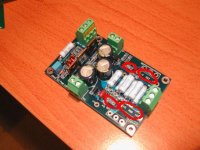
Your blue color cap for C5 is beginning to make me wonder too. What is the vendor name and part # for your C5 and C6?
Yours is correct according to Brian's Excel Spread sheet and the picture he took of his boards.
Also please note that there are differences in resistors between your and Jason's boards.
I will get the exact componet numbers and post them.
I wasn't aware that there are differences in resistors value between Jason's part list and Brians's part list - that is what you meant, right? In any case, I followed Brian's part list/number & it worked fine.
Member
Joined 2002
fcel said:I wasn't aware that there are differences in resistors value between Jason's part list and Brians's part list - that is what you meant, right? In any case, I followed Brian's part list/number & it worked fine.
He is talking about the A30 list and Mini a List.
Let me clear my statements:
R17, 18, 19, 22, 27 and 28 are different in the 3 (three) instances of the pictures in post # 777 and 778 and the kit I was sent from Jason.
Also C5 and C6 are different between the two posts (#777, 778). This is an easy fix as I will go by Brian's Excel SS and the blue cap will go to C6. Which means I did not get either (one of is missing) C4 or C5 in my kit...
I completely understand the fact that Jason's is a Mini-A and Fcel's is an A30... But why the difference in main board components(R17, 18, 19, 22)?
Member
Joined 2002
I'll see if I can help a little.
From this spreadsheet http://www.diyamps.com/aleph/docs/miniALEPH-parts_list.xls there are actually two spreadsheet in one. One is for A30 and the other is for mini-A. The resistor values ARE different - for those resistors that you have listed. The value for C5 and C6 are the same though for both amp.
I'm probably making this more confusing or have misunderstood you but may be Jason has already clear it with you.
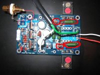
Jason's
.... Waiting 60 seconds...................
EDIT:
While waiting it stuck me what the 1/4 watt resistors were also and there should be three of them on my output boards instead!!
Well I guess those were not in the 2 kits I ordered either...
I guess my naivety got the best of me here.... I NEVER contemplated incomplete kits! Ok one cap no biggie... But now we're talking 2 caps and 12 resistors per kit x 2 kits. Now I see why I have been scratching my head.
Edit 2: Atrocious spelling.
Attachments
Cheer up, mate.
Don't be too hard on yourself, Troy. It is actually a bit confusing with all those different varieties on the same board Just take a look at the A-X boards ver 1.0😉 It would be a lot easier if it was like; one PCB, one BOM, one amp🙂
Steen🙂
Don't be too hard on yourself, Troy. It is actually a bit confusing with all those different varieties on the same board
Just take a look at the A-X boards ver 1.0😉 It would be a lot easier if it was like; one PCB, one BOM, one amp🙂 Steen🙂
Tweeker said:Is this the zener that is recommended to be bypassed by 1-4.7uF as a mod?
Yes, I'm pretty sure its a mod to possibly lower noise. Absolutely optional and experimental I think. I don't think Nelson used it in commercial versions but I certainly recall him offering it as a potential upgrade. He suggested starting with 1uf and possibly more. The higher the value the more turn on thump you may get.
regards
Ok I bought some 2% Metal film resistors @ Fry's yesterday for the output boards.
They were out of 220 Ohm, so I bought 200 and 470.
Which should I use? The 200 or 2(two) parallel 470's?
How critical is that 20Ohms? It is 20% of the value... I can either go 20 down or 15 up from the spec'ed 221....
They were out of 220 Ohm, so I bought 200 and 470.
Which should I use? The 200 or 2(two) parallel 470's?
How critical is that 20Ohms? It is 20% of the value... I can either go 20 down or 15 up from the spec'ed 221....
The 220 Ohm resistors are not really critical. The 220 Ohm will get you enough margin to prevent oscillation while maintining enough speed.
Go higher, say 470 - 820 Ohm and have more safety with less speed.
Go lower, say 50 - 100 Ohm and enjoy high speed with high risk of oscillations.
(I actually have achieved 22 amps at 11Mhz...and winded up with super heated FET's)
Go higher, say 470 - 820 Ohm and have more safety with less speed.
Go lower, say 50 - 100 Ohm and enjoy high speed with high risk of oscillations.
(I actually have achieved 22 amps at 11Mhz...and winded up with super heated FET's)
Tarasque said:The 220 Ohm resistors are not really critical. The 220 Ohm will get you enough margin to prevent oscillation while maintining enough speed.
Go higher, say 470 - 820 Ohm and have more safety with less speed.
Go lower, say 50 - 100 Ohm and enjoy high speed with high risk of oscillations.
(I actually have achieved 22 amps at 11Mhz...and winded up with super heated FET's)
Thanks Tarasque for the reply. I did error on the side of caution and went the parallel 470 route so I have 235 Ohms in each position. Now I just need to order the caps...
22 amps @ 11Mhz!!! Doing radio transmissions? Applied for your broadcaster’s license? 😀
chipco3434 said:Any need to match ouput devices on the mini?
Not really, since there is only one gain FET per channel, but if you're a purist perhaps you would like left and right to be exactly the same 🙂
I'm missing a couple items on amp board... nothing serious. In the position of R12, a 750 ohm, would a substitute of 820 (in the kit) or a 680 (on the bench) be the better choice?
- Status
- Not open for further replies.
- Home
- Amplifiers
- Pass Labs
- New Aleph Mini PCB GB