Finished up one PSU today. Parts for the second one are arriving tomorrow. I forgot to order LEDs, but my neighbor restores vintage video game consoles and likely has plenty from which to choose. Side note, remember when those vintage video games were new? <reflect here/>
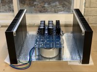
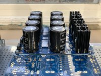
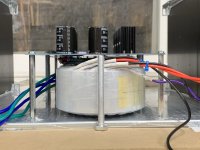
Anyway, I pondered a few different configurations with a friend who has built a couple of Pass amps, and his biggest concern was balance when moving. Good point. I thought about stacking the transformers either horizontally or vertically with a bracket. But in both cases it threw the majority of the enclosure weight to either end. As I was sifting through some mounting hardware, I ran across some substantial 1/4” x 3” (6.3mm x 76mm) standoffs. A Eureka moment came to me and I chose to mount the transformers side-by-side on the floor with the PSU boards forming a mezzanine across the top. That way I can feed then secondaries into the rectifier board from the bottom keeping the appearance squeaky clean. On top of that (so to speak), the runs from the LV side of the board only have to travel a few inches to the amplifier boards. I think this is going to turn out nicely.
Also, per ZM’s suggestion, I’ll be elevating the bottom plate about 10mm. Not sure I’ll have any wiring beneath the plate, but it’s not a bad idea. Still thinking about how the HV side is going to run.
Attachments
-
 29875395-622C-4968-B5B2-67B04EBD2D9C.jpg766 KB · Views: 247
 -
 20774E48-976F-4C9A-829F-D28C6805FCB0.jpg548.8 KB · Views: 254
 -
 BA6DD7A3-9D06-41BF-8132-D91F081D13FB.jpeg773.4 KB · Views: 247
 -
 9E420340-738C-432D-83CD-24CBE6AA1EBC.jpeg518.7 KB · Views: 264
 -
 F499E348-AB32-4961-83A2-8BAD30A04768.jpeg544.1 KB · Views: 245
 -
 253D70EA-6AF5-4FE5-BD7F-6F068C20098B.jpeg756.3 KB · Views: 178
Last edited:
Finished up one PSU today. Parts for the second one are arriving tomorrow. I forgot to order LEDs, but my neighbor restores vintage video game consoles and likely has plenty from which to choose. Side note, remember when those vintage video games were new? <reflect here/>
Anyway, I pondered a few different configurations with a friend who has built a couple of Pass amps, and his biggest concern was balance when moving. Good point. I thought about stacking the transformers either horizontally or vertically with a bracket. But in both cases it threw the majority of the enclosure weight to either end. As I was sifting through some mounting hardware, I ran across some substantial 1/4” x 3” (6.3mm x 76mm) standoffs. A Eureka moment came to me and I chose to mount the transformers side-by-side on the floor with the PSU boards forming a mezzanine across the top. That way I can feed then secondaries into the rectifier board from the bottom keeping the appearance squeaky clean. On top of that (so to speak), the runs from the LV side of the board only have to travel a few inches to the amplifier boards. I think this is going to turn out nicely.
Also, per ZM’s suggestion, I’ll be elevating the bottom plate about 10mm. Not sure I’ll have any wiring beneath the plate, but it’s not a bad idea. Still thinking about how the HV side is going to run.
Looking good Chris!
That looks great! I do not have the gift for chassis layouts. Three quick thoughts...
1) Clearance to boards once the donuts are mounted on their pads/rings. Looks like it will fit, but check to be doubly sure.
2) For suuuuuuper clean, you can direct solder or friction fit the secondaries to the bottom side of the boards.
3) Don't forget the friendly reminder that if you raise the perforated plate, that you check where it will be in relation to the bottom mounting holes from your rails on the heatsinks to the mounting holes on the front and back panels. They're a bugger to get to if you don't check in advance. I've said a few choice words after forgetting. Right ready to button everything up, and...
See...
🙂


 🤐
🤐 

1) Clearance to boards once the donuts are mounted on their pads/rings. Looks like it will fit, but check to be doubly sure.
2) For suuuuuuper clean, you can direct solder or friction fit the secondaries to the bottom side of the boards.
3) Don't forget the friendly reminder that if you raise the perforated plate, that you check where it will be in relation to the bottom mounting holes from your rails on the heatsinks to the mounting holes on the front and back panels. They're a bugger to get to if you don't check in advance. I've said a few choice words after forgetting. Right ready to button everything up, and...
See...
🙂
🤐 Nice layout, great progress.
And what Itsallinmyhead said, just went through that bonehead move.
And what Itsallinmyhead said, just went through that bonehead move.
That looks great! I do not have the gift for chassis layouts. Three quick thoughts...
1) Clearance to boards once the donuts are mounted on their pads/rings. Looks like it will fit, but check to be doubly sure.
2) For suuuuuuper clean, you can direct solder or friction fit the secondaries to the bottom side of the boards.
3) Don't forget the friendly reminder that if you raise the perforated plate, that you check where it will be in relation to the bottom mounting holes from your rails on the heatsinks to the mounting holes on the front and back panels. They're a bugger to get to if you don't check in advance. I've said a few choice words after forgetting. Right ready to button everything up, and...
See...
🙂
View attachment 932206
View attachment 932207
Thanks for the tips. The transformer mounting hardware certainly has my attention. I haven’t drilled the base for the mounting hardware yet but it’s tops on my list to watch.
Great minds think alike. My plan is to direct solder from the bottom. 😀
Hmmm... reckon I need to pay more attention to the bottom plate before making a move. I wondered if it was going to interfere with the semis and other parts. Seems like it may be more trouble than convenient.
Last edited:
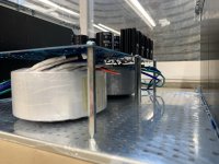
1) Clearance to boards once the donuts are mounted on their pads/rings. Looks like it will fit, but check to be doubly sure.
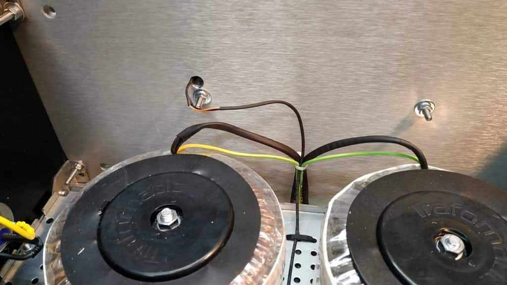
The plate and donuts clear, no problem. Going to have to take some length off of that bolt, though...
Attachments
Well, reckon it’s time to consider other options.Nice layout, great progress.
And what Itsallinmyhead said, just went through that bonehead move.
Nah...
For the back panel, make sure you have a tool that can reach the nut through the gap in the back panel and the plate or move the plate up or down. I use needle-nose pliers, but even a small boxhead might work well.
The front panel is a bit more tricky and should take priority, IMO. I should have taken a pic of that, but you'll get the idea when you lay the parts together. Since you have to screw directly into the front panel, you need to be able to get a screwdriver in-line with the axis of the screw 'into the chassis' or get really creative... or stupid... or both.
Mainly... there's plenty of vertical room to play with... just don't be a dodo like me and set it "right where it shouldn't be" <cough> TWICE.
You still get a pass if you only do it once after being reminded. 😀
Edited to add - there's no compelling reason to do it at all if you're not running wires under the baseplate/above the bottom cover. Even if you plan to do it, there's plenty of room between the bottom cover and the perforated plate (when it's not inverted) except at the edges.
tl;dr - if you're going down through a hole in the perforated plate and back up through another hole... I wouldn't worry about it.
Last edited:
regarding base plate - Mighty ZM is elevating it for 10mm, lip upside
when you're using 400deep case, no problems with front and back screws
who sez that 4U/400 is Modushop Swiss Knife case for Greedy Boyz?
and ya all are still buying sissy 300deep
except some Down Under, buying Big Compensator cases

easiest ......... or easier mounting of front plate - instead of 4mm screws, pre-mount headless 4mm screws on FP, say 15mm long
that way - much easier wrestling with washer, split washer and nut, than poking to start common screw in hole, in tight place
have adequate picture in some of my building strips, but lazy to search now
when you're using 400deep case, no problems with front and back screws
who sez that 4U/400 is Modushop Swiss Knife case for Greedy Boyz?
and ya all are still buying sissy 300deep
except some Down Under, buying Big Compensator cases
easiest ......... or easier mounting of front plate - instead of 4mm screws, pre-mount headless 4mm screws on FP, say 15mm long
that way - much easier wrestling with washer, split washer and nut, than poking to start common screw in hole, in tight place
have adequate picture in some of my building strips, but lazy to search now
Last edited:
^ +1 🙂
I stole it from him, he tells it right, I looked at his posts, and I still got it wrong the first two times.
I am never too busy to visit ZM's blog. 😀
These show the pics described above.
SissySIT, another one – Zen Mod Blog
An alternative (which honestly works very well) is to just mount the front panel before putting in the base plate. You can do that before or after you install the amp boards. I usually install the amp boards first, then just slide in the base plate. The back panel is actually easy even after you install the base plate. Don't mean to scare you, just provide some caution against repeating my boneheaded mistakes. Everything done except two silly screws to be installed by a screwup. 😀
It all works...
I’ll have plenty of room to experiment. I’ll give it a go and see what shakes out. May say a couple of naughty words in the process. But that’s part of the adventure I guess. 🙂
I am definitely following this post. I have been toying with doing something very similar for my Klipsch Fortes with the ALK crossover.
who sez that 4U/400 is Modushop Swiss Knife case for Greedy Boyz?
and ya all are still buying sissy 300deep
I guess many are buying the 300 deep chassis because of the availability
of UMS heatsinks...so the natural question is why not make a 4U/400 deluxe
chassis available?
Ideally the fets should be central on the heatsink and the fins running vertically.
Mounting the fets at the top of the heatsink is obviously not a wise idea but being below the centre line won't make too much difference.
My Aleph J does produce a fair bit of heat and its heatsinks are considerably bigger than those.
Mounting the fets at the top of the heatsink is obviously not a wise idea but being below the centre line won't make too much difference.
My Aleph J does produce a fair bit of heat and its heatsinks are considerably bigger than those.
I guess many are buying the 300 deep chassis because of the availability
of UMS heatsinks...so the natural question is why not make a 4U/400 deluxe
chassis available?
I'm asking that all the time, but nada
OK, I know that 6L6 is flying all the time, either in Air, or in Clouds
(last way pretty known to me) , so no offence from my side
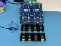
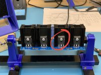
One thing I meant to mention yesterday but forgot was hole sizes. Since I used larger standoffs, I had to widen the holes a bit on the boards. The standard mounting hole size on the PSU boards is 3mm. Since I went with a 1/4” stand-off, I had enlarge the holes to 11/64” (4.4mm) to accommodate the #8-32 screws used with the standoffs. That’s probably as large as you would want to go. Beyond that the screw heads and washers will get close to things that go zap. Looking at my closeup photos, I might remove the washers and use some Loctite instead. Standard mounting holes circled in red below, enlarged holes circled in green.
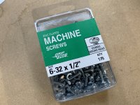
Since my local hardware store was low on metric screws, I crossed my fingers and bought something close for the rectifier/heat sink matings. Lady Luck was on my side and #6-32 screws fit perfectly.
Since my local hardware store was low on metric screws, I crossed my fingers and bought something close for the rectifier/heat sink matings. Lady Luck was on my side and #6-32 screws fit perfectly.
Attachments

- Home
- Amplifiers
- Pass Labs
- New Aleph J builder from Wisconsin, USA