They are great assets, no doubt. I’m a fan. Many hours of entertainment. 🙂
I’ll muddy the waters and vote for using the discrete bridges particularly as you have the floor space in the chassis.
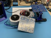
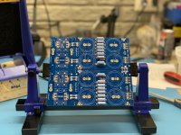
Knocked out some resistors and jumpers on my first PSU tonight. Just for kicks, decided to go with the discreet bridge. If it doesn’t work out, I can cut it off and go a different direction. As 6L6 said, nothing but room in this case, so let’s have some fun with it. #resistanceisfutile
Attachments
Last edited:
Four (4) it is. Now, I actually did this on purpose the spark discussion. I’ve spent hours and hours searching these and other discussions looking for guidance on whether to populate the “optional” resistors or not. It seems it’s based on capacitor charge current requirements and the current draw of the end device.
In post 82 of the power supply build thread, it was suggested to use all seven of the (parallel) resistors for an F5T. Presumably, because the current draw is higher, the lower resistance permits the power supply capacitors to recover more quickly. And as an Aleph J has lower current requirements, one might conclude that the caps’ recovery delta is less. This based on what I gleaned from this discussion:
How to calculate proper R value for RC filters in amplifier power supply - Electrical Engineering Stack Exchange
If I missed the mark, I’m happy to learn a thing or two. Otherwise I’m content with the “because I said so” answer. Works for my kids. 🙂. But it appears to be a common question, so hope any answers provided here are useful to future builders.
Attachments

Aside from security and connection quality, any other reasons why it may be more beneficial to solder the transformer leads to the rectifier board rather than using fast-on connectors? Serviceability is certainly improved with a friction connector.
I don't know of any benefits other than what you've listed for direct soldering.
From #87
I am sure others will chime in, if I am way off the mark. I am learning this, and I'm still dodgy. So, take below with a handful of salt.
I think the simplified answer is - More resistors of the same value in parallel will reduce the voltage drop at the expense of higher ripple.
Since you have dual mono PSUs with big toroids and are running an amp that won't draw a relative boatload of current, there's no need to sacrifice the ripple reduction for what would likely be an inconsequential rise in rail voltage.
I don't think the amount of time that it takes to charge / discharge the caps is relevant unless it takes longer than ~8.3ms to fully charge them, or inversely if they fully discharge faster than ~8.3ms.
That's a WAG, but I thought I'd give it a shot.
One factor to consider is that the Aleph J is single ended whereas the F5T is push-pull. Push-pull amplifiers in Class A have higher power supply rejection ratio (PSRR) due to phase cancellation so they can tolerate more power supply ripple without being noisy, whereas single ended amplifiers do not have the phase cancellation of push-pull amplifiers.
I don't know of any benefits other than what you've listed for direct soldering.
From #87
I am sure others will chime in, if I am way off the mark. I am learning this, and I'm still dodgy. So, take below with a handful of salt.
I think the simplified answer is - More resistors of the same value in parallel will reduce the voltage drop at the expense of higher ripple.
Since you have dual mono PSUs with big toroids and are running an amp that won't draw a relative boatload of current, there's no need to sacrifice the ripple reduction for what would likely be an inconsequential rise in rail voltage.
I don't think the amount of time that it takes to charge / discharge the caps is relevant unless it takes longer than ~8.3ms to fully charge them, or inversely if they fully discharge faster than ~8.3ms.
That's a WAG, but I thought I'd give it a shot.
One factor to consider is that the Aleph J is single ended whereas the F5T is push-pull. Push-pull amplifiers in Class A have higher power supply rejection ratio (PSRR) due to phase cancellation so they can tolerate more power supply ripple without being noisy, whereas single ended amplifiers do not have the phase cancellation of push-pull amplifiers.
I see, so it’s a matter of slowing things down, not speeding them up, to keep ripple at a minimum. A balancing act, no doubt. Appreciate your insights. Good knowledge!
I never considered that, Ben! Very cool.
Chris, if you'll indulge a wall of text 🙂 I had done this yesterday for my own curiosity. Since, Ben is referenced below, he may also have some insight to offer.
I am starting to get familiar with PSUD to see how things work. I used one of Ben's posts along with a few others to find a starting point.
diyAudio Power Supply Circuit Board v3 illustrated build guide
For the sim (and in my actual amp) I used almost all the same components listed in that post. I'm also using a dual mono PSU, so one channel's current for one PSU. For a single supply, it would double the current required.
4 x 0R47 in parallel => 0R1175
ESR for each 18,000 uF cap is ~0R026 if I did the math correctly. You can check the data sheets for yours. 2 in parallel before the resistors and 2 after. Equivalent Capacitance before and after => 36,000uF Equivalent ESR ~0R013 for each pair in parallel.
Antek AS-4218 - Antek doesn't provide regulation % in the data sheet, but I tried to derive it.
https://www.electronics-tutorials.ws/transformer/voltage-regulation.html
I'm not running the supply at full load. So, I measured it directly. This is data measured from my BA-3.
No load voltage (no input or output boards connected to PSU) - 18V75 AC
Full load voltage (amp fully biased and all boards connected) - 18V70 AC
Regulation => ~0.27%
I think that's the proper way to do it... but I am not certain. I looked at the data sheets for the 300VA 4218 and up to the 600VA 6218, and it started to click. The secondary voltage at higher power for the higher VA transformers is closer to the target voltage. Better regulation. Until I read the article over and over, I had thought a higher regulation % was better. Oops. I still may have it wrong.
I didn't bother entering in the data for my actual discrete diodes. That got a bit complex, and I really just wanted to see the effect of changing various values in the CRC. So, I chose the monolithic GBPC3504 bridge, which is probably relatively similar to the 3502 commonly suggested.
Below is just to show the directionality with two constant current loads and two sets of pi resistor values and be "close enough".
Constant current load of 1A5 PSUD shows:
Output voltage min 23.379 max 23.247 = Avg 23.408.
Ripple is +- ~20mV
If I increase the load to 2A625 (my bias current for BA-3),
Output voltage min 22.376 max 22.472 = Avg 22.424.
Ripple is +- ~47mV
My dissipation (not including the front end) is ~120W, so nicely within the 2x to 3x margin for ratio of transformer VA to total dissipation.
If I wanted to add resistors of the same value (say 7 total) - Plug in 0R067 for pi resistor
Constant current load of 1A5 PSUD shows:
Output voltage min 23.434 max 23.512 = Avg 23.473.
Ripple is +- ~39mV
Constant current load of 2A625 PSUD shows:
Output voltage min 22.477 max 22.606 = Avg 22.542.
Ripple is +- ~65mV
Running dual mono with the same 0R1175.
Constant current load of 5A25 PSUD shows:
Output voltage min 20.209 max 20.378 = Avg 20.306
Ripple is +- ~85mV
Total dissipation (not including the front end) will be 240W. 400VA/240 .. That's above the rule of thumb, and the resulting sag is apparent.
Again, those are just examples. I also did not increase the regulation% (reduce performance) of the transformer as current increased in the last example. The voltage sag would have likely been even worse, but this was for fun. However, when I match the sim to some of the measured voltages on my BA-3, it's pretty close. My guess is that my discrete diodes don't drop quite the same voltage as the big monolithic. I still can't measure PSU ripple properly in situ, but I'm learning.
Below is a shot of the last sim in case you want to try PSUD. It took me a while to figure out how to adjust things, derive specs etc., and I'm still not totally confident. However, it definitely shows directionality.
Enjoy the Aleph J. Loving the pics of progress. 😀


Edited to use consistent terms: Lower regulation % => better performance. I think
Chris, if you'll indulge a wall of text 🙂 I had done this yesterday for my own curiosity. Since, Ben is referenced below, he may also have some insight to offer.
I am starting to get familiar with PSUD to see how things work. I used one of Ben's posts along with a few others to find a starting point.
diyAudio Power Supply Circuit Board v3 illustrated build guide
For the sim (and in my actual amp) I used almost all the same components listed in that post. I'm also using a dual mono PSU, so one channel's current for one PSU. For a single supply, it would double the current required.
4 x 0R47 in parallel => 0R1175
ESR for each 18,000 uF cap is ~0R026 if I did the math correctly. You can check the data sheets for yours. 2 in parallel before the resistors and 2 after. Equivalent Capacitance before and after => 36,000uF Equivalent ESR ~0R013 for each pair in parallel.
Antek AS-4218 - Antek doesn't provide regulation % in the data sheet, but I tried to derive it.
https://www.electronics-tutorials.ws/transformer/voltage-regulation.html
I'm not running the supply at full load. So, I measured it directly. This is data measured from my BA-3.
No load voltage (no input or output boards connected to PSU) - 18V75 AC
Full load voltage (amp fully biased and all boards connected) - 18V70 AC
Regulation => ~0.27%
I think that's the proper way to do it... but I am not certain. I looked at the data sheets for the 300VA 4218 and up to the 600VA 6218, and it started to click. The secondary voltage at higher power for the higher VA transformers is closer to the target voltage. Better regulation. Until I read the article over and over, I had thought a higher regulation % was better. Oops. I still may have it wrong.
I didn't bother entering in the data for my actual discrete diodes. That got a bit complex, and I really just wanted to see the effect of changing various values in the CRC. So, I chose the monolithic GBPC3504 bridge, which is probably relatively similar to the 3502 commonly suggested.
Below is just to show the directionality with two constant current loads and two sets of pi resistor values and be "close enough".
Constant current load of 1A5 PSUD shows:
Output voltage min 23.379 max 23.247 = Avg 23.408.
Ripple is +- ~20mV
If I increase the load to 2A625 (my bias current for BA-3),
Output voltage min 22.376 max 22.472 = Avg 22.424.
Ripple is +- ~47mV
My dissipation (not including the front end) is ~120W, so nicely within the 2x to 3x margin for ratio of transformer VA to total dissipation.
If I wanted to add resistors of the same value (say 7 total) - Plug in 0R067 for pi resistor
Constant current load of 1A5 PSUD shows:
Output voltage min 23.434 max 23.512 = Avg 23.473.
Ripple is +- ~39mV
Constant current load of 2A625 PSUD shows:
Output voltage min 22.477 max 22.606 = Avg 22.542.
Ripple is +- ~65mV
Running dual mono with the same 0R1175.
Constant current load of 5A25 PSUD shows:
Output voltage min 20.209 max 20.378 = Avg 20.306
Ripple is +- ~85mV
Total dissipation (not including the front end) will be 240W. 400VA/240 .. That's above the rule of thumb, and the resulting sag is apparent.
Again, those are just examples. I also did not increase the regulation% (reduce performance) of the transformer as current increased in the last example. The voltage sag would have likely been even worse, but this was for fun. However, when I match the sim to some of the measured voltages on my BA-3, it's pretty close. My guess is that my discrete diodes don't drop quite the same voltage as the big monolithic. I still can't measure PSU ripple properly in situ, but I'm learning.
Below is a shot of the last sim in case you want to try PSUD. It took me a while to figure out how to adjust things, derive specs etc., and I'm still not totally confident. However, it definitely shows directionality.
Enjoy the Aleph J. Loving the pics of progress. 😀
Edited to use consistent terms: Lower regulation % => better performance. I think
Last edited:

Wow, that’s quite enlightening! Completely opposite of how I thought it worked. Your wall of text is fantastic research, worthy of a thesis (to me anyway). I’m tickled that you would take the time to compose it. Many thanks to you. I’m confident that others will find it useful, too!I never considered that, Ben! Very cool.
Chris, if you'll indulge a wall of text 🙂 I had done this yesterday for my own curiosity. Since, Ben is referenced below, he may also have some insight to offer.
I am starting to get familiar with PSUD to see how things work. I used one of Ben's posts along with a few others to find a starting point.
diyAudio Power Supply Circuit Board v3 illustrated build guide
For the sim (and in my actual amp) I used almost all the same components listed in that post. I'm also using a dual mono PSU, so one channel's current for one PSU. For a single supply, it would double the current required.
4 x 0R47 in parallel => 0R1175
ESR for each 18,000 uF cap is ~0R026 if I did the math correctly. You can check the data sheets for yours. 2 in parallel before the resistors and 2 after. Equivalent Capacitance before and after => 36,000uF Equivalent ESR ~0R013 for each pair in parallel.
Antek AS-4218 - Antek doesn't provide regulation % in the data sheet, but I tried to derive it.
https://www.electronics-tutorials.ws/transformer/voltage-regulation.html
I'm not running the supply at full load. So, I measured it directly. This is data measured from my BA-3.
No load voltage (no input or output boards connected to PSU) - 18V75 AC
Full load voltage (amp fully biased and all boards connected) - 18V70 AC
Regulation => ~0.27%
I think that's the proper way to do it... but I am not certain. I looked at the data sheets for the 300VA 4218 and up to the 600VA 6218, and it started to click. The secondary voltage at higher power for the higher VA transformers is closer to the target voltage. Better regulation. Until I read the article over and over, I had thought a higher regulation % was better. Oops. I still may have it wrong.
I didn't bother entering in the data for my actual discrete diodes. That got a bit complex, and I really just wanted to see the effect of changing various values in the CRC. So, I chose the monolithic GBPC3504 bridge, which is probably relatively similar to the 3502 commonly suggested.
Below is just to show the directionality with two constant current loads and two sets of pi resistor values and be "close enough".
Constant current load of 1A5 PSUD shows:
Output voltage min 23.379 max 23.247 = Avg 23.408.
Ripple is +- ~20mV
If I increase the load to 2A625 (my bias current for BA-3),
Output voltage min 22.376 max 22.472 = Avg 22.424.
Ripple is +- ~47mV
My dissipation (not including the front end) is ~120W, so nicely within the 2x to 3x margin for ratio of transformer VA to total dissipation.
If I wanted to add resistors of the same value (say 7 total) - Plug in 0R067 for pi resistor
Constant current load of 1A5 PSUD shows:
Output voltage min 23.434 max 23.512 = Avg 23.473.
Ripple is +- ~39mV
Constant current load of 2A625 PSUD shows:
Output voltage min 22.477 max 22.606 = Avg 22.542.
Ripple is +- ~65mV
Running dual mono with the same 0R1175.
Constant current load of 5A25 PSUD shows:
Output voltage min 20.209 max 20.378 = Avg 20.306
Ripple is +- ~85mV
Total dissipation (not including the front end) will be 240W. 400VA/240 .. That's above the rule of thumb, and the resulting sag is apparent.
Again, those are just examples. I also did not increase the regulation% (reduce performance) of the transformer as current increased in the last example. The voltage sag would have likely been even worse, but this was for fun. However, when I match the sim to some of the measured voltages on my BA-3, it's pretty close. My guess is that my discrete diodes don't drop quite the same voltage as the big monolithic. I still can't measure PSU ripple properly in situ, but I'm learning.
Below is a shot of the last sim in case you want to try PSUD. It took me a while to figure out how to adjust things, derive specs etc., and I'm still not totally confident. However, it definitely shows directionality.
Enjoy the Aleph J. Loving the pics of progress. 😀
View attachment 931980
Edited to use consistent terms: Lower regulation % => better performance. I think
Also, in the years I’ve been around electronics, I’ve never seen fractional EIRW values expressed as I have seen here. I love it! It makes everything so compact and perfectly understandable. A new standard for me!
Last edited:
I'm glad it helped. It's a blast for me to begin understanding even a tiny bit about what's happening under the hood and how things connect.
I don't have any electronics background at all. I started using the xRxx, xAxx, xVxx nomenclature after observing it here. In other work, I commonly see decimal points and commas used interchangeably due to cultural norms. That can cause confusion. Scientific notation is preferred for work, but I think the xRxx etc, is easier to "scale" and show relative values. It's also easier to type in the forum software. 0R47 or 4.7x10^-1 ohms or 470mohms or 0,47ohms or 0.47ohms.
I was too lazy to re-type the cut-and-pasted values from PSUD. I also still haven't seen a typically used convention for capacitance. Maybe b/c it spans the gamut so widely in common usages. 36,000uF or 0F036 or 36mF
3.6pF => 0F0000000036. 3.6pF is easier to type and not forget a significant 0.
I get so much "noise" from inductive coupling (I think) to the probes and poor scope technique that I can never get it where I feel confident.
You always provide confidence, it's greatly appreciated. 😀
You always provide confidence, it's greatly appreciated. 😀
remember, this is not dialysis 🙂
though, also remember not to trust too much in Jokester's words; at least when our Main Jokester is in case, heavy work and frightening experience is behind every joke
though, also remember not to trust too much in Jokester's words; at least when our Main Jokester is in case, heavy work and frightening experience is behind every joke
I also still haven't seen a typically used convention for capacitance. Maybe b/c it spans the gamut so widely in common usages. 36,000uF or 0F036 or 36mF
3.6pF => 0F0000000036. 3.6pF is easier to type and not forget a significant 0.
milli micro nano pico femto............
🙂
- Home
- Amplifiers
- Pass Labs
- New Aleph J builder from Wisconsin, USA