Hi folks,
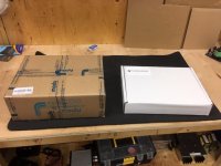
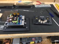
When you open the box, you are rewarded with two more: One with the box (er, I mean enclosure 🙂) and one with Tom's stuff.
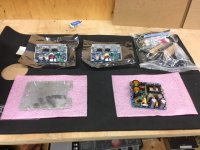
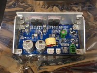
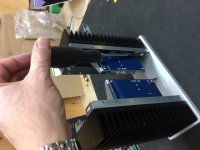
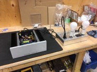
Tom's stuff includes two modules, the switching power supply, and a bag of goodies. Speaking of the modules, they are pretty impressive. Mechanically they are very solid and look like they will be easy to mount - having just one mounting surface (the heatsink) very much simplifies the mechanical design. They are also well laid out and assembled - they are quality looking boards. Here's some photos:
When you open the box, you are rewarded with two more: One with the box (er, I mean enclosure 🙂) and one with Tom's stuff.
Tom's stuff includes two modules, the switching power supply, and a bag of goodies. Speaking of the modules, they are pretty impressive. Mechanically they are very solid and look like they will be easy to mount - having just one mounting surface (the heatsink) very much simplifies the mechanical design. They are also well laid out and assembled - they are quality looking boards. Here's some photos:
Attachments
Gentlemen,
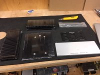
The HiFi-2000 metalwork is top-shelf as always. As you likely know, Tom is a big fan of Torx screws. This didn't pose a problem for me as I've got a collection of Torx screwdrivers ... until I got to the ones that hold the standoffs to the bottom. These are Torx T8 screws, which I didn't have a screwdriver for! A quick trip to canadian tire solved that little problem. You might want to check your collection for the smaller drivers.
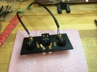
The wiring harness had very clear instructions and I had no problem. Actually I lie - I managed to use the wrong 'yellow' crimp connectors for the wrong part of the harness. oops. I had some spare ones, so no issue - but please confirm the exact size of your connectors before you attach them.
Back plate inputs are connected and wired. Yes I am an unbalanced individual.
The HiFi-2000 metalwork is top-shelf as always. As you likely know, Tom is a big fan of Torx screws. This didn't pose a problem for me as I've got a collection of Torx screwdrivers ... until I got to the ones that hold the standoffs to the bottom. These are Torx T8 screws, which I didn't have a screwdriver for! A quick trip to canadian tire solved that little problem. You might want to check your collection for the smaller drivers.
The wiring harness had very clear instructions and I had no problem. Actually I lie - I managed to use the wrong 'yellow' crimp connectors for the wrong part of the harness. oops. I had some spare ones, so no issue - but please confirm the exact size of your connectors before you attach them.
Back plate inputs are connected and wired. Yes I am an unbalanced individual.
Attachments
Here's the modules with the thermal compound. I can't say enough about the mechanical design of these modules. The physical aspects of them are great - it's a clever design.
The instructions said to assemble the heatsinks to the face plate, then attach the modules to the heatsinks afterwards. I found this to be impossible to do because my Torx drivers don't allow you to work at an angle. Instead, I attached the modules to the heatsinks then attached the heatsinks to the front plate.
We're getting there!
Attachments

Folks,
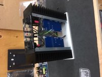
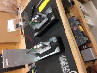
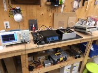
The amp is together and alive. here's some shots. I found that the best way to get the back plate on was to first screw on the bottom plate to pull the heatsinks in the proper position, then attach the back plate. Tom says in the instructions that this is the most challenging part of the build. He is right!
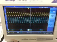
I brought up the unit on the dim-bulb tester. This thing has saved my *** on more than one occasion. After making sure that the rail voltage was right, I attached a signal generator, dummy load, and a scope.
Looks like there's a signwave on the scope! More testing in a bit.
The amp is together and alive. here's some shots. I found that the best way to get the back plate on was to first screw on the bottom plate to pull the heatsinks in the proper position, then attach the back plate. Tom says in the instructions that this is the most challenging part of the build. He is right!
I brought up the unit on the dim-bulb tester. This thing has saved my *** on more than one occasion. After making sure that the rail voltage was right, I attached a signal generator, dummy load, and a scope.
Looks like there's a signwave on the scope! More testing in a bit.
Attachments
That's awesome! Thank you for sharing your build experience. I'm looking forward to hearing about your subjective experience of the amp and sound quality as well.
Torx screws: Yeah. I like 'em. The bits don't slip and scratch up your chassis unlike Philips screws. The Torx bits deliver good torque to the screws. I think the black screws are actually Torx-Plus, so even better than Torx. Thankfully, you can use a regular Torx driver with them.
If I recall correctly, the kit requires: T-8, T-10, 2.5 mm hex, and Philips #2 to assemble. At least I meant to include screws with 2.5 mm socket heads for the amp modules (M4 x 6 mm) as I figured more people would have a 2.5 mm hex key than a stubby T-10. From your description it sounds like they might have been Torx. With Torx you can always use an SAE hex key. I think it's a 3/32" that fits in a T-10. You can also get Torx keys that are shaped like hex keys (if that sentence makes any sense).
Thanks for taking the time to post the build pictures. I appreciate it.
Tom
Last edited:
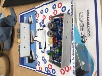
hey what's that red digikey board? looks like a board to measure stuff or bend passives? have a link for it?Gentlemen,
The HiFi-2000 metalwork is top-shelf as always. As you likely know, Tom is a big fan of Torx screws. This didn't pose a problem for me as I've got a collection of Torx screwdrivers ... until I got to the ones that hold the standoffs to the bottom. These are Torx T8 screws, which I didn't have a screwdriver for! A quick trip to canadian tire solved that little problem. You might want to check your collection for the smaller drivers.
The wiring harness had very clear instructions and I had no problem. Actually I lie - I managed to use the wrong 'yellow' crimp connectors for the wrong part of the harness. oops. I had some spare ones, so no issue - but please confirm the exact size of your connectors before you attach them.
Back plate inputs are connected and wired. Yes I am an unbalanced individual.
thank you
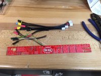
It's a Digikey ruler that they sent out as a freebee sometime this past year. P/N: PCB-RULER-ND
I don't think it's useful for bending passives, but for figuring out hole sizes and such, it's semi-useful. Mine lives on my desk and I use it occasionally when designing PCBs.
Tom
I don't think it's useful for bending passives, but for figuring out hole sizes and such, it's semi-useful. Mine lives on my desk and I use it occasionally when designing PCBs.
Tom
It's a Digikey ruler that they sent out as a freebee sometime this past year. P/N: PCB-RULER-ND
I don't think it's useful for bending passives, but for figuring out hole sizes and such, it's semi-useful. Mine lives on my desk and I use it occasionally when designing PCBs.
Tom
thank you! is there anything useful or that you can recommend to bend the passives? or the term to look for it myself. thank you again
Last edited:
Mayfly - your work area is far too tidy. 😉
To be honest, I made the same mistake with the yellow connectors on the wiring harnesses, but also had spares.
I built mine with XLR inputs, as one of my pre-amps has balanced outputs, and use pseudo-balanced interconnects for other applications.
Quite a fun project.
To be honest, I made the same mistake with the yellow connectors on the wiring harnesses, but also had spares.
I built mine with XLR inputs, as one of my pre-amps has balanced outputs, and use pseudo-balanced interconnects for other applications.
Quite a fun project.
Yep - I think they mailed it out to everyone with a corporate account a few years ago. Mine lives in the workshop. It's actually a PCB 🙂
thank you! is there anything useful or that you can recommend to bend the passives? or the term to look for it myself. thank you again
The best thing to use is one of those plastic lead benders. Here's some:

Mayfly - your work area is far too tidy. 😉
To be honest, I made the same mistake with the yellow connectors on the wiring harnesses, but also had spares.
I built mine with XLR inputs, as one of my pre-amps has balanced outputs, and use pseudo-balanced interconnects for other applications.
Quite a fun project.
Thanks man! I figure you only build the thing once, so may as well take your time.
BTW, I've done some more testing, and here's what I found:
1 - Tom's power output figures for the modules are accurate 🙂. I pulled 67 watts RMS into 8 ohms before clipping with my unit.
2 - On attempting to measure the THD, I found that I could not measure anything above the noise floor of the signal generator! This means that a) Tom's design is pretty linear and b) my signal generator sucks. I used to have access to an AP at my old work, but sadly now have to rely on older stuff that I can afford...
thank you! is there anything useful or that you can recommend to bend the passives?
Needle nose pliers? Honestly, I've been at it so long that my hands are calibrated for bending resistors to 0.4" lead spacing. I do it by feel.
I am really impressed with the quality!
Thank you.
To be honest, I made the same mistake with the yellow connectors on the wiring harnesses, but also had spares.
Yeah... There are two types of yellow QC connectors in the kit. 6.3 x 0.8 mm and 4.75 x 0.5 mm. The 6.3 x 0.8, you can get at any auto parts store. The smaller size (especially 0.5 mm tab thickness) is harder to come by. In the final version of the design documentation (which will be available later today) I do list the part numbers in case you need more of them.
1 - Tom's power output figures for the modules are accurate 🙂. I pulled 67 watts RMS into 8 ohms before clipping with my unit.
Perfect!
2 - On attempting to measure the THD, I found that I could not measure anything above the noise floor of the signal generator!
Welcome to my world. 🙂 Even with the APx525, I'm struggling to measure the THD. I need to get my distortion microscope built. I'm think it'll be an updated and improved version of Cordell's Distortion Magnifier (Linear Audio Vol. 0), which itself is an implementation of Baxandall's summing circuit.
Tom
The best thing to use is one of those plastic lead benders. Here's some:
Those look perfect, ty!
Folks,
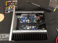
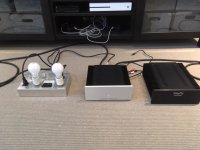
Had a chance to have a good listen to the amp and do some comparisons. Here's what I found:
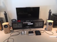
1 - the amp is dead quiet. There was no discernible hum or hiss coming from the speakers.
2 - on listening, everything sounds as it should. I'm personally not a big fan of subjective listening tests because there is so much that can bias them, but I will say that there are no defects that I can hear. No distortion, no strange phase stuff, full frequency response, 'sounds good to me' sound stage, etc, etc. Thumbs up from the sitting on the couch and cranking the tunes department.
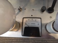
3 - when running the amp does not use much power. It would not even deflect the needle on the current meter. Stays cool as well.
4 - A direct comparison to a fairly pedestrian LM3886 amp of my own design showed that the two amps sounded pretty much the same. Now I must point out that I can measure THD in my design, but I cannot with Tom's. That is saying something. Also my design is larger, heavier, and about 25 watts down on power 🙂.
Here's some pics: Note the Linkwitz Plutos in the background (which are why I'm into LM3886s in the first place!)
Had a chance to have a good listen to the amp and do some comparisons. Here's what I found:
1 - the amp is dead quiet. There was no discernible hum or hiss coming from the speakers.
2 - on listening, everything sounds as it should. I'm personally not a big fan of subjective listening tests because there is so much that can bias them, but I will say that there are no defects that I can hear. No distortion, no strange phase stuff, full frequency response, 'sounds good to me' sound stage, etc, etc. Thumbs up from the sitting on the couch and cranking the tunes department.
3 - when running the amp does not use much power. It would not even deflect the needle on the current meter. Stays cool as well.
4 - A direct comparison to a fairly pedestrian LM3886 amp of my own design showed that the two amps sounded pretty much the same. Now I must point out that I can measure THD in my design, but I cannot with Tom's. That is saying something. Also my design is larger, heavier, and about 25 watts down on power 🙂.
Here's some pics: Note the Linkwitz Plutos in the background (which are why I'm into LM3886s in the first place!)
Attachments
In terms of accessing tricky screws I find two extreme approaches useful.I found this to be impossible to do because my Torx drivers don't allow you to work at an angle. Instead, I attached the modules to the heatsinks then attached the heatsinks to the front plate.
We're getting there!
I have a large set of 1/4" hex bits (they're cheap...) and use EITHER a driver plus a 12" extender bar (which stops the handle of the driver fouling) OR a tiny ratchet.
Screwdriver Bit / Hex / Adaptor / Power Bit Extension (300mm) Magnetic TE441: Amazon.co.uk: DIY & Tools
DRAPER 17 PIECE OFFSET RATCHET SCREW AND SOCKET DRIVER SET(DRAPER 811SXA): Amazon.co.uk: DIY & Tools
These get you "most places" (at least in my experience to date)
BugBear
- Home
- Vendor's Bazaar
- Neurochrome Modulus-286: 65W (8Ω); 125W (4Ω) @ <-120dB THD Composite Amplifier Module