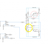
One has its emitter connected to the base of the outputs via a 2.7 ohm resistor. That's the one I have circled.
The one you circled has no connection to the base of the output transistor.
The one you circled has no connection to the base of the output transistor.
What's the DC voltage across the 150 ohm resistor between its emitter and the secondary center-tap?
Post the same for the corresponding transistor in the other channel.
Post the same for the corresponding transistor in the other channel.
Depending on which direction I measure it +/- 12.45v.
The corresponding resistor on the other channel is +/- 0.73v
The corresponding resistor on the other channel is +/- 0.73v
Check the DC voltage across all of the orange diodes near the 5534 for that channel. All should read approximately what the other channel read (0.65v).
I'm assuming you meant the channel with low voltage(right channel). All of the orange diodes near the 5534 are reading approximately 0.645v, one was 0.647, and another 0.648.
The left channel was approximately the same the lowest being 0.644v the highest being 0.660v.
The left channel was approximately the same the lowest being 0.644v the highest being 0.660v.
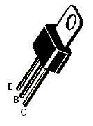
While we are on the subject of MPSU57 and MPSU07 do you happen to know of a suitable replacement for them?
CEN-U07 and CEN-U57 are generally good subs.
What's the base to emitter voltage for that transistor with the amp on, black probe on the emitter?
What's the base to emitter voltage for that transistor with the amp on, black probe on the emitter?
Base to emitter voltage for that transistor is +.52v.
I also measured the corresponding transistor on the other side of the board as well and it is at +0.60v.
I then again measured the voltage across the 150 ohm resistor that previously had +/- 12.45v...It now is reading +/- 0.85v.
I still have rail voltage. Although I did notice the PS FET's on the left channel side of the board are getting hot fairly rapidly. The other side is staying cool. I checked the driver voltage on both sides and it even on each side.
The voltage across the 150 ohm resistor has changed significantly. Does the amp still cut out like it was doing?
Why did the voltage change if no components were replaced?
If I'm not mistaken, each power supply has its FETs on both sides of its transformer. If there is a problem, it's likely a drive problem. You need to compare left/right (side of transformer) drive from the 494 to the FETs to see if there is a difference. This includes the DC voltage on the collectors of the NON drivers and the PNP drivers.
While no components were replaced there was one very large component removed...the heat sink. I found that there was small piece of the thermal tape scraped away next to one of the screw holes. The output transistor next to that screw hole was intermittently grounding out on that spot. So the voltage had changed because being out of the heat sink the output transistor was not grounding out.
I compared the left/right (side of transformer) drive from the 494 to the FETs to see if there is a difference and they are exactly the same. As well as the the DC voltage on the collectors of the NON drivers and the PNP drivers. As you said, "if there is a problem". It has been my experience that when I power up an amp(out of the heat sink) on my power supply and it is functioning 100% as it should, none of the components get hot or even warm, excluding the transformer. The components that are getting hot(out of the heat sink) on this amp are two PS FET's on the left side and the two voltage regulators on the right side, which I mentioned before. Is that unusual? There doesn't seem to be a problem with those components when the amp is clamped in the heat sink. That is, using my IR thermometer the temperature readings are even on both sides of the PS FET's and output transistors, including the voltage regulators.
Wanted to get your thoughts on those components getting hot before I check the amp to see if it is cutting out like it was before. I suspect that it will no longer cut out.
Regulators can get hot (to the point of failing without being clamped to the heatsink).
Many in the PPI amps will fail after a few minutes. I've had one regulator fail within seconds from overheating in an MTX amp.
If the left side regulators are powering a different load (they're not left 'channel' regs on one side and right channel regs on the other side), they will operate at different temperatures.
If they're not failing, off of the heatsink, I wouldn't worry about them. They have protection circuits that are supposed to protect them from thermal and over-current conditions.
All of the power supply FETs should operate at approximately the same temperature. The two that are getting hot may have a slightly lower threshold and are taking the majority of the load. You can try swapping them out or moving them to see if the problem follows the FETs in question or the location where they were installed.
There is definitely a power supply problem going on with it. One of the PS FET's blew on the side I mentioned had a couple getting hot, while I was testing the amp output.
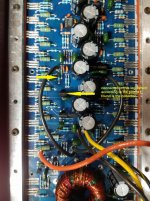
I must be over looking something as I can find nothing out of balance. Pins 9 and 10 are both at +2.5v. I've tested the MPsA06's divers and MPSA56,s circled in the photo.
I must be over looking something as I can find nothing out of balance. Pins 9 and 10 are both at +2.5v. I've tested the MPsA06's divers and MPSA56,s circled in the photo.
Attachments
- Status
- Not open for further replies.
- Home
- General Interest
- Car Audio
- Needing help repairing an Orion HCCA 250 Digital Reference